


3
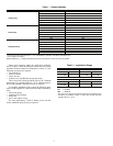
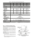
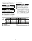
Table 3A — Physical Data, Under Ceiling Cooling Only Units
*Field reconfigured to 18,000 Btuh (1
1
/
2
tons). See Before Installa-
tion section on this page for details.
† The valve connection size is
7
/
8
inch. The recommended line size
is 1
1
/
8
inch.
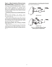
Step 1 — Complete Pre-Installation Checks
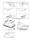
UNPACK UNIT — Store fan coil unit in the original packag-
ing until it is moved to the final site for installation. When re-
moving unit from carton, lift unit by its 4 corners; DO NOT lift
unit by its plastic parts.
INSPECT SHIPMENT — Upon receipt of shipment, check
fan coil unit for damage. Forward claim papers directly to the
transportation company. Manufacturer is not responsible for
damage incurred in transit.
Check all items; if any item is missing, notify your dealer.
To prevent loss or damage, leave all parts in original packages
until installation.
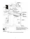
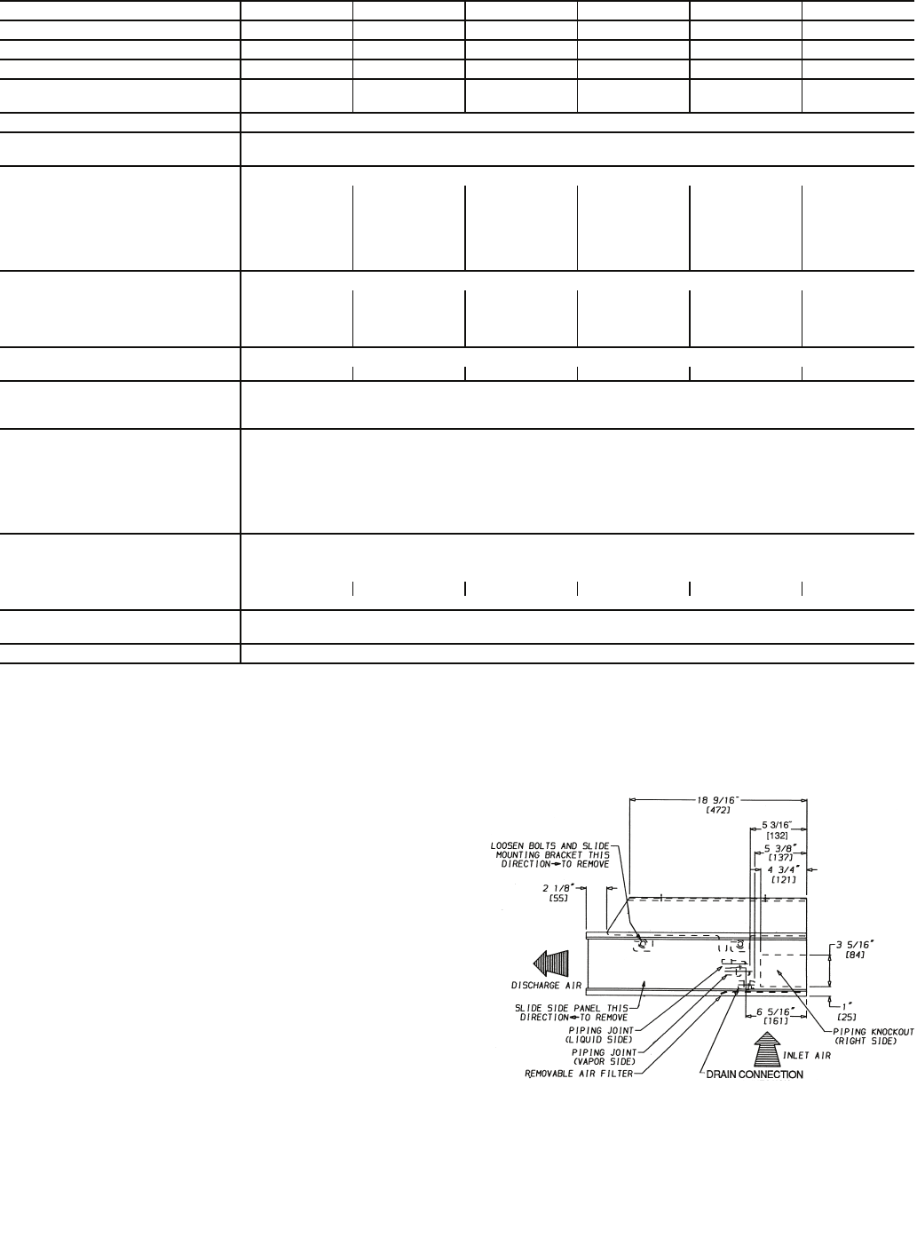
BEFORE INSTALLATION — Perform the following steps
before installing indoor fan coil unit. Place the indoor unit up-
side down on the floor, then:
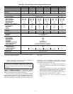
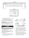
1. Remove side panels by sliding forward, then away
from sides of unit (Fig. 2). Reinstall prior to unit start-
up.
2. Remove air filters from inlet grilles; then remove and
retain screws securing inlet grilles to indoor unit. Rein-
stall prior to unit start-up.
SYSTEM SIZE 018* 024 030 036 048 060
NOMINAL CAPACITY (tons) 1
1
/
2
23345
NOMINAL SIZE (Btuh) 18,000 24,000 30,000 36,000 48,000 60,000
OPERATING WEIGHT (lb) 108 108 117 117 149 179
MOISTURE REMOVAL WEIGHT
(Pints/Hr)
4.0 7.3 6.0 9.0 13.0 14.5
FINISH GM Motorhome White with Black Trim
REFRIGERANT R-410A
Control (Cooling) AccuRater Control
INDOOR FAN Direct Drive Centrifugal
Rpm...Cfm High 862...500 1050…600 1275...840 1275...840 1435...1200 1275...1600
Rpm...Cfm Medium 690...400 690...400 972...740 972...740 1388...1160 972...1220
Rpm...Cfm Low 552...320 552...320 830...640 830...640 1315...1100 830...1040
High Speed Watts 92 92 282 282 425 564
Motor Quantity 111122
Blowers — No. ...Size (in.) 2...6x8 2…6x8 2…6x8 2…6x8 3…6x8 4…6x8
INDOOR COIL Copper Tube, Aluminum Fin
Face Area (sq ft) 2.2 2.2 2.6 2.6 3.0 4.0
No. of Rows 444444
Fins/in. 14.9 14.9 14.9 14.9 14.9 14.9
Circuits 444488
FILTERS Cleanable
Quantity 445568
AIRSWEEP
Horizontal User select ON/OFF
Vertical Manual
CONTROLS
Control Voltage 24 V
Auto Restart Ye s
Fan Speed High/Medium/Low
Condensate Pump Safety Yes (Accessory)
Indoor Coil Freeze Protection Standard shutoff at 28 F
Filter Change Indication 250 Hours of Indoor Fan Operation
REFRIGERANT LINES
Connection Type Flare
Liquid Line OD (in.)
3
/
8
Vapor Line OD (in.)
5
/
8
5
/
8
3
/
4
3
/
4
7
/
8
7
/
8
†
Max Line Length For maximum line lengths see condensing unit instructions.
CONDENSATE DRAIN
CONNECTION
Pipe Thread (MPT)
CONDENSATE DRAIN SIZE (in.)
3
/
4
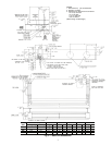
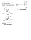
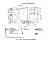
NOTE: Dimensions shown in brackets [ ] are in mm.
Fig. 2 — Removal of Mounting Brackets
from Indoor Unit