


18
START-UP
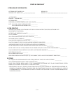
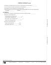
Make the following checks and complete the Start-Up
Checklist on page CL-1 before system start-up. Also refer to
the condensing unit Installation, Start-Up and Service Instruc-
tions for system start-up instructions and refrigerant charging
methods.
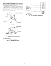
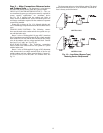
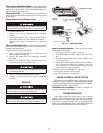
1. Check condensate drainage system:
a. Remove grille and frame from the unit.
b. On the opposite side of the drain connection, insert
a water bottle up into the fan coil unit and fill drain
pan. Refer to Fig. 22. Water must flow steadily; if
not, check the pipe slope or inspect for any pipe
restrictions.
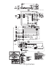
2. Make sure that all wiring connections are correct and
that they are tight.
3. Check that all barriers, covers, and panels are in place.
Ensure that the filters and return-air grilles have been
installed and that the discharge louvers are positioned
correctly.
After Extended Shutdown — If the system has been
turned off for more than 12 hours and a crankcase heater is be-
ing used, turn on the indoor and outdoor unit disconnect
switches to supply power to the system for 12 hours BEFORE
starting the system.
Seasonal Changeovers — When changing heat pump
system from cooling to heating or heating to cooling, or before
starting cooling only system after it has been out of use for the
winter season, perform the following steps BEFORE starting
the system:
1. Inspect and clean the outdoor unit, particularly the
coil.
2. Clean or replace the air filters in the indoor unit.
3. Clean the indoor unit drain pan and drain pipe, and
remove any obstructions.
4. If the outdoor unit is equipped with a crankcase heater,
turn on indoor and outdoor unit disconnect switches to
supply power to the system 12 hours before starting
the system.
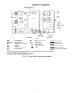
Adjusting Airflow
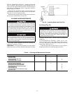
AUTOMATIC AIR SWEEP — All units are equipped with
an air sweep feature which directs the airflow louvers up and
down to provide optimum room air circulation. The air sweep
function can be controlled by the toggle switch located on the
lower right corner of the unit. If using a thermostat with an air
sweep switch, see Fig. 20 and 21 for wiring modifications.
Operating Mode Memory — After the system is
turned off or after a power failure, the system remains in the
last operating mode selected. When the system is turned back
on, or when power is automatically restored, operation contin-
ues in the same operating mode as when the system shut down.
Automatic Operation (Auto.) Mode — If auto.
mode is selected, the system automatically switches over the
operating mode from heating to cooling, or from cooling to
heating (heat pump system only) depending on the selected
temperature. Auto. mode also controls fan speed if not manual-
ly overridden.
NOTE: Between the cooling cycle and the heating cycle there
is a neutral zone of approximately 2° F above and 2° F below
the selected temperature when only the fan is operating.
Operating Sequence — Ceiling-suspended fan coil
units have a relay board which controls system operation in re-
sponse to a room thermostat. The user may manually select any
one of 3 fan speeds for unit operation. Ceiling-suspended sys-
tems may be equipped with an accessory power ventilation kit
and/or condensate pump.
FAN OPERATION — Fan coils are capable of 3-speed opera-
tion. See thermostat instructions for fan speed selection. When
the fan(s) is operating in medium or high speed and the unit is
equipped with the power ventilation kit, the ventilation fan will
operate to provide fresh air.
COOLING MODE OPERATION — When the room ther-
mostat senses a demand for cooling, the fan coil relay board is
energized. The indoor fan(s) will start in the selected speed (if
it is not already operating). The reversing valve (heat pump
only) will energize for cooling operation.
The internal condensate pump (if so equipped) runs when-
ever the reversing valve is energized (heat pump only) and/or
the unit is in cooling. As long as the condensate float switch
and freeze protection thermostat are closed, the cooling relays
in the fan coil unit will close. This energizes the compressor
and outdoor fan in the outdoor unit. The compressor will con-
tinue to operate until the room thermostat is satisfied. When the
cooling demand is satisfied, the compressor and outdoor fan
will stop. If the system is in the AUTO. position, the indoor fan
will stop with the compressor. If the unit has the accessory ven-
tilation kit, the ventilation fan will operate whenever the indoor
fan is set for medium or high speed.
HEAT PUMP OPERATION — When the room thermostat
senses a demand for heating the indoor fan will start in the
selected speed (if not already operating), and the reversing
valve will not be energized. The internal condensate pump (if
supplied) and freeze protection thermostat are not operated
during heating operation. The control relay (CR2) closes, and
the compressor and outdoor fan are energized through the de-
frost board (DFB), which is located in the outdoor unit. The
microprocessor logic in the DFB is energized when the com-
pressor starts, and the defrost timer runs. Once every 90 min-
utes (factory default setting) of compressor run time, the DFB
logic checks the defrost thermostat (DFT). If the DFT is open,
the unit continues in heating operation. If the DFT is closed, the
DFB switches the unit to defrost mode. The timing on the DFB
may be set at either 30, 50, or 90 minutes.
DEFROST (Heat Pump Only) — The DFB energizes the
RVS (reversing valve solenoid), and the reversing valve
switches to the cooling position. The K1 relay on the DFB
opens and the outdoor fan stops. The W2 contact on the DFB is
also energized, which in turn energizes the defrost relay on the
fan coil relay board, turns off the electric heater and stops the
indoor fan.
The DFB logic checks the 10-minute defrost timer and the
DFT. If the DFT opens in less than 10 minutes, the DFB
switches the unit back to normal heating operation. If the DFT
remains closed, the DFB switches the unit back to heating op-
eration after 10 minutes. When the DFB changes back to heat-
ing mode, the RVR (reversing valve relay) is deenergized and
the reversing valve switches back to heating operation. Both
the outdoor and indoor fans come back on, and if necessary, the
electric heater also turns on.
SYSTEM SAFETIES — The system is equipped with the
following safety devices to protect system components:
Indoor coil freeze protection thermostat — If a coil temper-
ature of 28 F or lower is sensed, the compressor and outdoor
fan will be shut down until the coil temperature exceeds 28 F.
The indoor fan will continue to run.
Condensate float switch (units equipped with accessory
condensate pump, cooling cycle only) — If the level of con-
densate in the drain pan rises too high, the condensate float
switch will turn the system off.
Never operate unit without a filter or with grille removed;
damage to the unit or personal injury may result.