


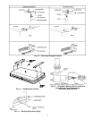
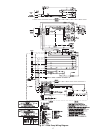
13
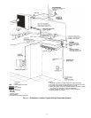
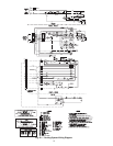
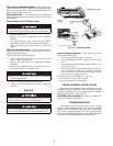
Step 8 — Make Connections Between Indoor
and Outdoor Units —
The thermostat is wired between
the indoor and outdoor units to make the system complete.
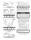
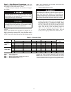
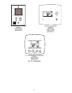
CHECK ACCURATER METERING DEVICE — The cor-
rect AccuRater (bypass type) refrigerant control is required for
system capacity optimization. An AccuRater device
(see Fig. 19) is supplied with the outdoor unit. Refer to
Tables 4A-4C to determine the correct AccuRater piston size
and charge combination required for the condenser/evaporator
system being installed.
Piston style as shown in Fig. 19 is shipped with the unit.
Do not interchange components between the AccuRater device
types.
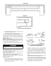
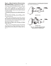
COOLING ONLY SYSTEMS — The following connec-
tions must be made to the outdoor unit for it to operate as a sys-
tem with the indoor unit:
Route 2 wires of field-supplied 18-gage AWG (American
Wire Gage) thermostat cable between the low-voltage terminal
block of the fan coil unit and the blue and brown low-voltage
wires in the outdoor unit low voltage terminal block. Connect
the wires Y1 to Y and C to C. See Fig. 19.
HEAT PUMP SYSTEMS — The following connections
must be made to the outdoor unit for it to operate as a system
with the indoor unit:
Route 5 wires of field-supplied 18-gage AWG thermostat
cable between the low-voltage terminal block of the fan coil
and the outdoor unit low-voltage terminal block. Connect Y1
to Y, R to R, O to O, W2 to W2, and C to C with the wires. See
Fig. 20.
The heat pump unit uses a timed defrost method. The timed
defrost can be field set for 30, 50, or 90 minutes. The timed de-
frost is factory set for 90 minutes.
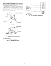
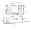
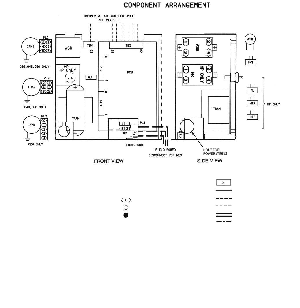
LEGEND
ASM — Air Sweep Motor
ASR — Air Sweep Relay
EQUIP GND — Equipment Ground
FL — Fuse Link
FPT — Freeze Protection Thermostat
HP — Heat Pump
HR — Heater Relay
HTR — Heater
HTT — Heater Temp. Thermostat
IFM — Indoor-Fan Motor
NEC — National Electrical Code
PL — Plug
TB — Terminal Board
TRAN — Transformer
Terminal (Marked)
Terminal (Unmarked)
Splice
Terminal Block
Factory Wiring
Field Power Wiring
Field Control Wiring
Printed Circuit Board
Accessory or Optional Wiring
NOTES:
1. If any of the original wire furnished must be replaced, it must be replaced with type 90 C wire or its equivalent.
2. Wire in accordance with NEC and local codes.
3. Transformer is thermally protected and will reset automatically.
4. Indoor-fan motor(s) are inherently thermally protected.
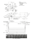
Fig. 17 — Control Circuit Connections Arrangement