


6
5. Run refrigerant piping as directly as possible and avoid
any unnecessary turns or bends.
6. Condensate piping can be directed through the inside
wall to an approved drain or straight outside.
NOTE: The piping hole for condensate line must slope at a
minimum pitch of
1
/
4
in. per foot to ensure proper drainage. If
proper pitch cannot be achieved, install accessory condensate
pump at this time.
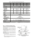
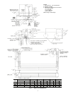
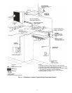
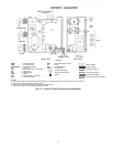
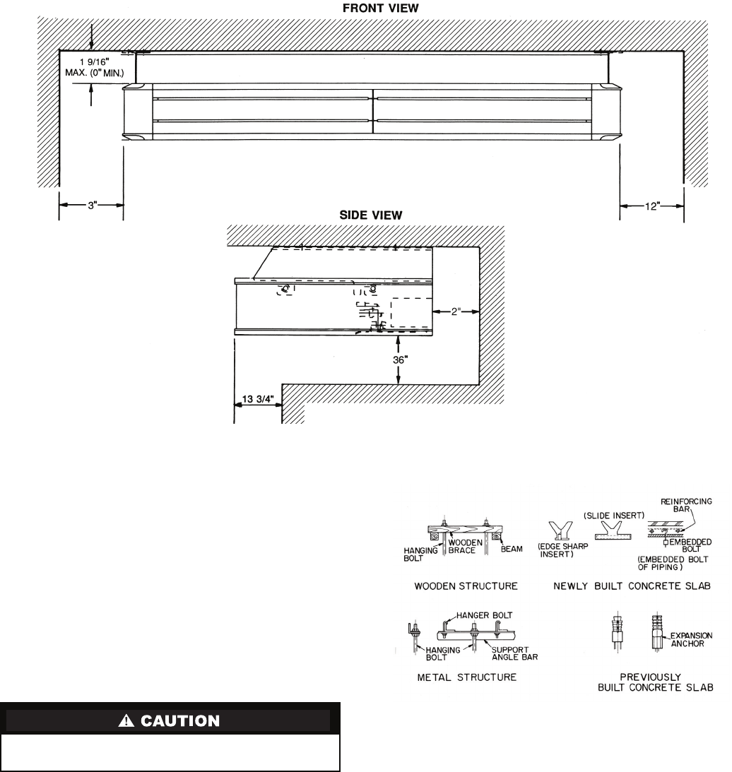
Step 3 — Mount Unit — Refer to Fig. 4 for clearances
and dimensions. Use mounting template included inside box to
locate mounting bolt holes, piping holes, electrical connec-
tions, and accessory outdoor-air intake, if used.
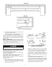
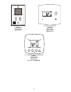
Select proper type of hardware from the guidelines below.
See Fig. 5.
WOODEN STRUCTURE — Install hanging bolts on a
square wooden piece placed over beams.
NEWLY BUILT CONCRETE SLAB — Install hanging bolts
with inserts, embedded bolts, etc.
METAL STRUCTURE — Install hanging bolts utilizing an
existing angle or by installing a new support angle.
PREVIOUSLY BUILT CONCRETE SLAB — Install hang-
ing bolts with expansion anchor.
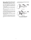
TO MOUNT UNIT:
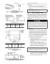
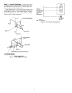
1. Remove mounting bracket and reinstall the 2 hex-head
bolts (factory-supplied) into each side of indoor unit as
shown in Fig. 6. Allow approximately
3
/
8
-in. space
between bolt head and unit.
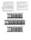
2. Determine installation position, paying particular
attention to piping lengths, wiring connections, clear-
ances, etc. See Fig. 3 for connection locations, Fig. 4
for clearances, and Fig. 7 and 8 for bolt locations.
3. Open knockout if right-side piping connections are
required (Fig. 9), by removing the pre-slit portion in
the rear of the right side panel with a saw or cutter
knife.
4. Mount hanging brackets on ceiling (Fig. 10) for either
concealed or exposed bolt hanging position.
5. Lift the unit into place, and fit the hex-head bolts on
sides of indoor unit into mounting slots of mounting
brackets (Fig. 11). Ensure unit is mounted with a slight
tilt to the right rear side for properly drainage.
6. Tighten indoor unit hex-head bolts securely.
Solid structure in ceiling must be used due to the weight of
the unit.
Fig. 4 — Fan Coil Unit Clearances
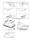
Fig. 5 — Fan Coil Unit Mounting Methods
(Hardware is Field-Supplied)