


4
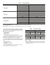
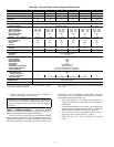
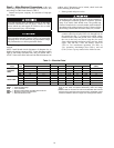
Table 3B — Physical Data, Under Ceiling Heat Pump Units
*Field reconfigured to 18,000 Btuh (1
1
/
2
tons). See Before Installa-
tion section on page 3 for details.
†The valve connection size is
7
/
8
inch. The recommended line size
is 1
1
/
8
inch.
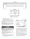
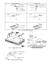
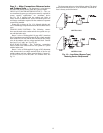
3. Remove inlet grilles from indoor unit by sliding for-
ward. Reinstall prior to unit start-up.
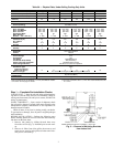
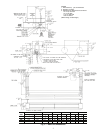
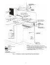
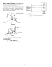
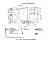
Step 2 — Select Location — Consult local building
codes and NEC for special installation requirements. See Fig. 3
and 4 for unit dimensions and required clearances.
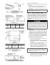
There are several ways the unit may be installed to different
types of ceiling construction. These instructions do not cover
all installation methods. As a typical installation, these instruc-
tions focus primarily on mounting the unit to metal in new
construction. Plan the installation carefully before you begin.
Listed below are some guidelines that should be followed
when determining location for the unit.
1. Place unit adjacent to an outside wall if fresh air is
required, ensuring that location allows for complete air
distribution.
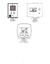
2. Locate the thermostat in an area that is not subjected to
drafts or direct sunlight through windows. Locate the
thermostat on an internal wall whenever possible.
3. Allow sufficient clearance for airflow, wiring, refriger-
ant piping, and servicing unit (Fig. 3 and 4).
4. Make sure the unit is easily accessible to electrical
power.
UNIT SIZE 018* 024 030 036 048 060
NOMINAL CAPACITY (tons) 1
1
/
2
23345
NOMINAL SIZE (Btuh) 18,000 24,000 30,000 36,000 48,000 60,000
OPERATING WEIGHT (lb) 110 110 119 119 151 181
MOISTURE REMOVAL WEIGHT
(Pints/Hr)
4.0 7.3 6.0 9.0 13.0 14.5
FINISH GM Motorhome White with Black Trim
REFRIGERANT R-410A
Control (Cooling) AccuRater Control
TXV
INDOOR FAN Direct Drive Centrifugal
Rpm...Cfm High 900…480 1050…550 1275...840 1275...840 1435...1130 1275...1600
Rpm...Cfm Medium 862...400 900…480 972...740 972...740 1388... 975 972...1220
Rpm...Cfm Low 770...320 862...400 830...640 830...640 1315... 820 830...1040
High Speed Watts 92 92 282 282 425 564
Motor Quantity 111122
Blowers — No. ...Size (in.) 2...6x8 2...6x8 2...6x8 2...6x8 3...6x8 4...6x8
INDOOR COIL Copper Tube, Aluminum Fin
Face Area (sq ft) 2.2 2.2 2.6 2.6 3.0 4.0
No. of Rows 444444
Fins/in. 14.9 14.9 14.9 14.9 14.9 14.9
Circuits 444488
FILTERS Cleanable
Quantity 445568
HEATERS (kW) 2.0 2.0 3.0 3.0 4.0 5.0
AIRSWEEP
Horizontal User select ON/OFF
Vertical Manual
CONTROLS
Control Voltage 24 V
Defrost Method Timed
Dehumidification Ye s
Auto Restart Ye s
Fan Speed High/Medium/Low
Condensate Pump Safety Yes (Accessory)
Filter Change Indication 250 Hours of Indoor Fan Operation
Freeze Protection Indoor coil less than 28 F, resets at 50 F.
REFRIGERANT LINES
Connection Type Flare
Liquid Line OD (in.)
3
/
8
Vapor Line OD (in.)
5
/
8
5
/
8
3
/
4
3
/
4
7
/
8
7
/
8
†
Max Line Length For maximum line lengths see condensing unit instructions.
CONDENSATE DRAIN
CONNECTION
Pipe Thread (MPT)
CONDENSATE DRAIN SIZE (in.)
3
/
4
IMPORTANT: If necessary, reconfigure the 24,000 Btuh
fan coil unit to 18,000 Btuh. Unplug the fan motor at the
control box harness and plug into the 40QA018 marked
connector.