


26
Step 4 — Make Electrical Connections
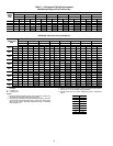
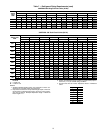
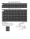
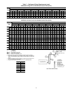
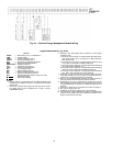
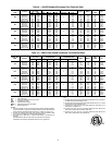
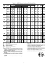
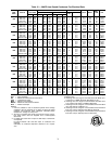
POWER SUPPLY — The electrical characteristics of the
available power supply must agree with the unit nameplate
rating. Supply voltage must be within the limits shown in
Tables 9-12. See Table 13 for incoming power options.
POWER WIRING — All power wiring must comply with
applicable local and national codes. Install field-supplied
branch circuit fused disconnect per NEC (National Electrical
Code, U.S.A) of a type that can be locked OFF or OPEN. Dis-
connect must be within sight and readily accessible from the
unit in compliance with NEC Article 440-14.
General Wiring Notes:
1. The control circuit does NOT require a separate power
source. Control circuit power is obtained by a step-down
transformer from the main three-phase power supply. Be
sure that the appropriate connection tap is connected on
all transformers for the supply voltage.
2. A low-voltage terminal strip (LVT) is provided for
field-wired control devices.
NOTE: The field-supplied disconnect should never be off
except when unit is being serviced or is to be down for a pro-
longed period.
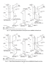
3. Power entry is at one end only.
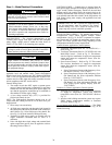
4. All field power enters the unit through a hole located in
the corner post of the unit or the bottom of the control box
shelf. Refer to Fig. 18 for field power wiring details. Re-
fer to Fig. 5-8 for exact location of field power entry.
5. Terminals for field power supply are suitable only for
copper conductors. Insulation must be rated 75 C
minimum.
6. Units with high short circuit ratings and terminal block
option require that specific fuses be applied to achieve
this rating. Refer to Table 13.
CONTROL POWER — Control power is obtained from the
main power supply and does NOT require a separate source. A
toggle switch (marked Emergency On-Off on the unit label
diagram and by the switch) allows the control circuit to be
manually disconnected when necessary. Crankcase heaters are
in an operable state when this switch is in the Off position. All
field control wiring must comply with applicable local and
national codes.
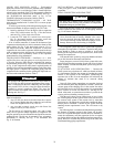
FIELD CONTROL WIRING — The standard unit control is
microprocessor based which supports multiple control
configurations. See Fig. 19 for EAT (evaporator air tempera-
ture sensor) and SAT (supply air temperature sensor) layout.
Figures 20-24 show specific field wiring, depending on unit
configuration and desired control requirements.
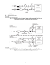
Constat Volume Application Control Options
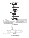
1. Two-Stage Thermostat (Part No. 33CS2PP2S-01) —
Refer to Fig. 20.
2. Two-Stage Thermostat (Part No. 33CS2PP2S-01) with
Multi-Step Control — Refer to Fig. 21. This thermo-
stat also requires installation of supply-air temperature
sensor and return-air temperature sensor (Part No.
33ZCSENSAT).
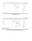
3. Space Sensor Control — Refer to Fig. 22. This control
also requires installation of supply-air temperature
sensor and return-air temperature sensor (Part No.
33ZCSENSAT).
a. Space Temperature Sensor with Occupancy Over-
ride Button (Part No. 33ZCT55SPT)
b. Space Temperature Sensor with Occupancy Over-
ride Button and Set Point Adjustment Slidebar
(Part No. 33ZCT56SPT)
c. Space Temperature Sensor with Occupancy Over-
ride Button, Set Point Adjustment Slidebar, and
LCD (liquid crystal display) Display (Part No.
33ZCT59SPT)
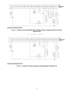
Variable Air Volume Application Control Options
1. Discharge-air temperature control requires installation
of supply-air temperature sensor and return-air
temperature sensor (Part No. 33ZCSENSAT). Refer to
Fig. 23.
2. Interface with building automation system may require
EMM (energy management module) or translator
accessory. Refer to Fig. 23.
Energy Management Module (EMM) Option
— The EMM
is available for factory or field installation. See Fig. 24 for
EMM field wiring.
WARNING
Before performing service or maintenance operations on
unit, turn off main power switch to unit. Electrical shock
could cause personal injury.
IMPORTANT: When starting up this equipment for
operation, be sure to check tightness of all electrical ter-
minal connections, clamps, screws, etc., as they may
have become loose during shipment. It is also advisable
to re-tighten all electrical connections after equipment
has been in operation and components have reacted to
operating temperature.
IMPORTANT: Operating unit on improper supply
voltage or with excessive phase imbalance constitutes
abuse and may adversely affect Carrier warranty.
CAUTION
Proper rotation of condenser fan(s) MUST be verified
before compressors are started. Consult the Controls, Start-
Up and Operation guide provided with the 38AP units for
correct procedure. Failure to comply could result in possi-
ble equipment damage.
IMPORTANT: For 208-v systems, the connection tap
for all transformers must be changed. The factory
default setting is for 230-v. Failure to connect to the
proper tap may result in unreliable operation.