


2
DOMESTIC UNITS — Standard 38AP unit packaging con-
sists of coil protection only. Skids are not provided. If overhead
rigging is not available at the jobsite, place the unit on a skid or
pad before dragging or rolling. When rolling, use a minimum
of 3 rollers. When dragging, pull the pad or skid. Do not apply
force to the unit. When in final position, raise from above to lift
unit off the pad or skid.
EXPORT UNITS — All export units are mounted on skids
with vertical coil protection. Leave the unit on the skid until it
is in final position. While on the skid, the unit can be rolled or
skidded. Apply force to the skid, not to the unit. Use a mini-
mum of 3 rollers when rolling. When in final position, raise
from above to remove the skid.
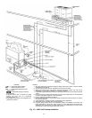
PLACING UNITS — When considering location of the unit,
be sure to consult National Electrical Code (NEC, U.S.A.) and
local code requirements. Allow sufficient space for airflow,
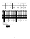
wiring, piping, and service. The placement area must be level
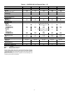
and strong enough to support the operating weight of the unit.
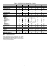
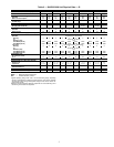
(See Table 5.) When unit is in proper location, use of mounting
holes in base rails is recommended for securing unit to
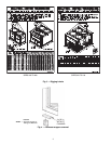
supporting structure. For mounting unit on vibration isolators,
4 x 24 in. perimeter support ASTM “C” channels between unit
and the isolators are recommended with a minimum of 4 chan-
nels per unit. Fasteners for mounting unit are field supplied.
See Fig. 4.
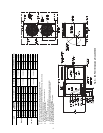
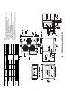
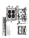
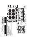
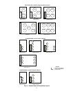
Refer to Fig. 5-8 for airflow clearances. Recommended
minimum clearances are 6 ft (1829 mm) for unrestricted air-
flow and service on sides of unit, 4 ft (1219 mm) on ends, and
unrestricted clear air space above the unit. Provide ample space
to connect liquid and suction lines to indoor unit. For multiple
units, allow 10 ft (3048 mm) separation between airflow
surfaces. If walls surround the unit, wall height should not ex-
ceed the top of the unit fan discharge. Installation in a pit is not
recommended.
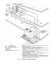
Refer to Fig. 9 for outdoor fan and compressor layout.
Refer to Fig. 10 and 11 for unit piping installation. See
Table 6 for refrigerant specialties part numbers.
IMPORTANT: Be sure to mount unit level to ensure
proper oil return to compressors.
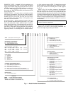
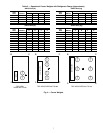
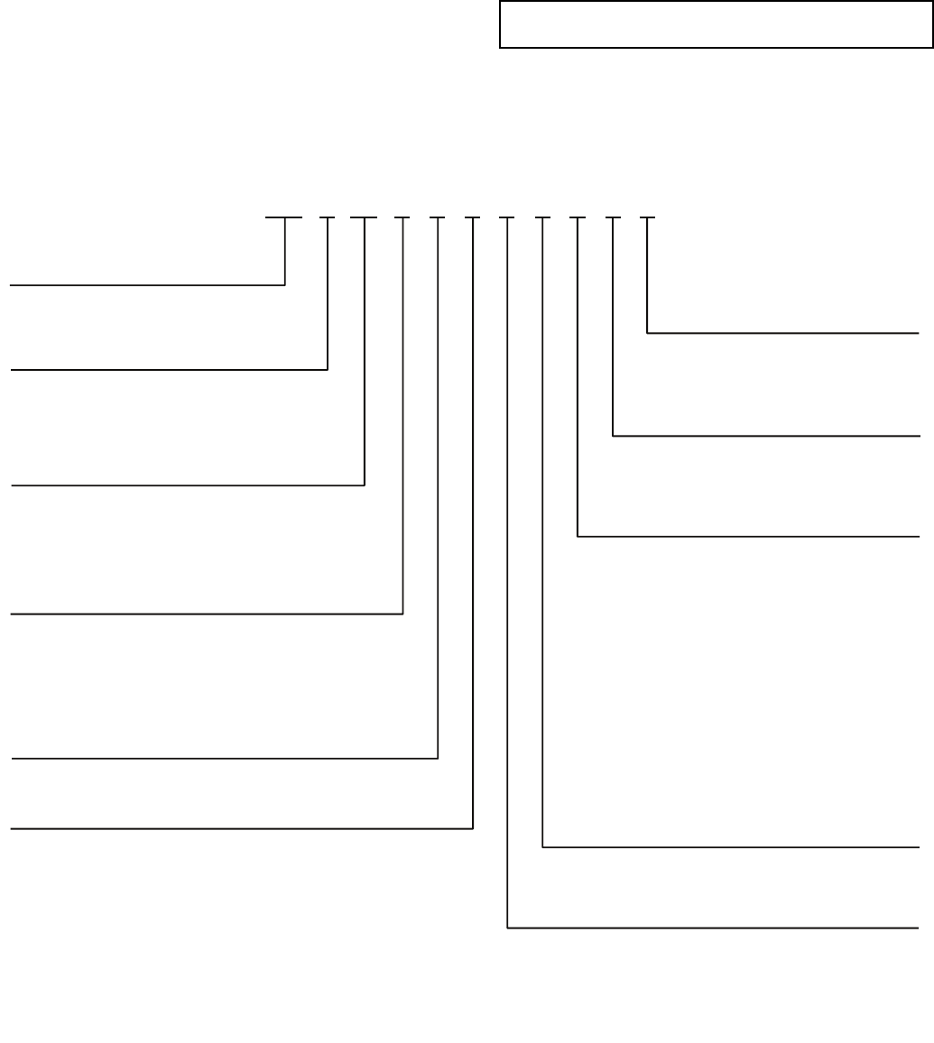
38AP D 025 6 4 A 1 0 0 5 0
38AP – Split System Condensing Unit Packaging/Security Options
0 – Std Packaging
8 – Std Packaging, Bottom Skid
J – Bottom Skid, Top Crate, Bag
Controls/Communications Options
2 – Scrolling Marquee
3 – EMM, Scrolling Marquee
5 – No Display
Ambient/Capacity Control/
Interrupt Options
0 – Std Ambient, Std Compressor,
Std Interrupt
2 – Std Ambient, Digital Compressor,
Std Interru
pt
3 – Std Ambient, Std Compressor,
High Interrupt
5 – Std Ambient, Digital Compressor,
High Interrupt
6 – Low Ambient, Std Compressor,
Std Interrupt
8 – Low Ambient, Digital Compressor,
Std Interrupt
9 – Low Ambient, Std Compressor,
High Interrupt
C – Low Ambient, Digital Compressor,
High Interrupt
Line Length Options
1 – Standard Line Length
2 – Long Line Length Check Valves
Electrical Options
0 – Single Point Power, Terminal Block
1 – Single Point Power,
Non-Fused Disconnect
Refrigeration Circuit Options
*
D – Dual Refrigeration Circuit
S – Single Refrigeration Circuit
Revision Level
A – Current Revision Level
ylppuS rewoP
1 – 575-3-60
2 – 380-3-60
5 – 280/230-3-60
6 – 460-3-60
9 – 380/415-3-50
Condenser Coil/Low Sound Options
4 – MCHX, No Sound Treatment
5 – E-coat, MCHX, No Sound Treatment
C – MCHX, Low Sound Fan(s)
D
– E-coat MCHX, Low Sound Fan(s)
H – MCHX, Low Sound Fan(s), Compressor Blankets
J – E-coat MCHX, Low Sound Fan(s), Compressor Blankets
Nominal Capacity – Tons (kW)
025 – 25 (88) 050 – 50 (176) 090 – 90 (317)
027 – 27 (95) 060 – 60 (211) 100 – 100 (352)
030 – 30 (106) 070 – 70 (246)
040 – 40 (141) 080 – 80 (281)
LEGEND
*38APS units available in sizes 025-050 only.
EMM — Energy Management Module
MCHX — Microchannel Heat Exchanger
a38-7100.eps
Fig. 1 — Model Number Nomenclature