


Step 2 — Rig and Mount the Unit
Be sure unit panels are securely in place prior to
rigging.
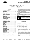
RIGGING — These units are designed for overhead rigging
only. For this purpose, the transverse base channels extend
beyond the sides of the unit, with holes provided in the end
plates to attach cables or hooks. Rig with top skid packaging
assembly in place to prevent unit damage by the rigging cable.
As further protection for the coil faces, plywood sheets can
be placed against the sides of the unit, behind the cables.
Run the cables to a central suspension point so that the angle
from the horizontal is not less than 45 degrees. Raise and set
the unit down carefully.
If it is necessary to roll the unit into position, mount
the unit on longitudinal rails, using a minimum of 3 rollers.
Apply force to the rails, not the unit. If the unit is to be skid-
ded into position, place it on a large pad and drag it by the
pad. Do not apply any force to the unit.
Raise from above to lift unit from the rails or pad when
unit is in final position.
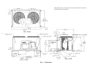
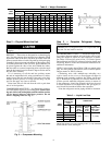
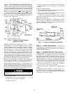
COMPRESSOR MOUNTING — As shipped, the compres-
sor is held tightly in place by self-locking bolts. Before start-
ing unit, loosen self-locking bolts until the snubber washer
can be moved sideways with finger pressure. Do not
remove shipping bolts. See Fig. 3.
Step 3 — Complete Refrigerant Piping
Connections
IMPORTANT:A refrigerant receiver is not provided with
the unit. Do not install a receiver.
SIZE REFRIGERANT LINES — Consider the length of pip-
ing required between outdoor unit and indoor unit (evapo-
rator), the amount of liquid lift, and compressor oil return.
See Tables 3-5B and also refer to Part 3 of Carrier System
Design Manual and E20-II software for design details and
line sizing. Refer to indoor unit installation instructions for
additional information.
NOTE: Use the piping data in Tables 3-5B as a general guide
only. For more precise calculations, refer to Carrier System
Design manual or E20-II software.
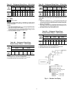
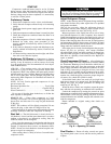
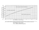
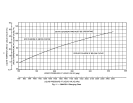
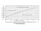
Condensing units with multiple-step unloading may
require double suction risers to assure proper oil return at
minimum load operating condition. See Tables 4A-5B and
Fig. 4. Reduction of evaporator coil surface should be ana-
lyzed to provide sufficient refrigerant velocity to return oil
to the compressor. Liquid line solenoid valves may be used
in certain situations to accomplish this. Hot gas bypass, if
used, should be introduced before the evaporator.
Note that refrigerant suction piping should be insulated.
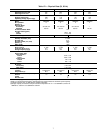
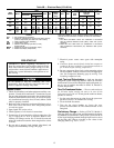
Table 3 — Liquid Line Data
UNIT
38AKS
MAXIMUM
ALLOWABLE
LIQUID LIFT
ft (m)
LIQUID LINE
60 Hz 50 Hz
Maximum
Allowable
Pressure
Drop
psig (kPa)
Maximum
Allowable
Temp.
Loss
F (C)
Filter Drier
and
Sight Glass
Flare Conn.*
in. (mm)
013 52 (15.8)
7 (48.3) 2 (1.1)
5
⁄
8
(15.88)
014 67 (20.4)
016 82 (25.0
024 87 (26.5) 86 (26)
*Inlet and outlet.
NOTE: Data shown is for units operating at 45 F (7.2 C) saturated
suction and 95 F (35 C) entering air.
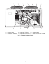
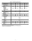
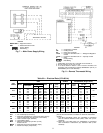
Table2—Weight Distribution
UNIT
38AKS
WEIGHT
Total
Operating
Support Point
ABCDEF
lb kg lb kg lb kg lb kg lb kg lb kg lb kg
013 732 332 94 43 93 42 93 42 149 68 151 68 152 69
013C 825 374 119 54 116 53 115 52 157 71 159 72 159 72
014 779 353 95 43 94 43 94 43 164 74 166 75 166 75
014C 919 417 131 59 129 59 128 58 176 80 177 80 178 81
016 789 358 95 43 95 43 96 44 167 76 168 76 168 76
016C 929 421 131 59 130 59 130 59 178 81 180 82 180 82
024 900 408 119 54 114 52 113 51 179 81 185 84 190 86
024C 1040 472 155 70 150 68 146 66 191 87 196 89 202 92
Fig. 3 — Compressor Mounting
8