


Winter Start Control (If Required) — Install Ac-
cessory Package 38AE900021.
Crankcase Heater — The heater prevents refrigerant
migration and compressor oil dilution during shutdown when-
ever compressor is not operating. It is wired to cycle with
the compressor; the heater is off when compressor is run-
ning, and on when compressor is off.
Both compressor service valves must be closed whenever
the crankcase heater is deenergized for more than 6 hours.
The crankcase heater is operable as long as the control cir-
cuit is energized.
Compressor Protection
CIRCUIT BREAKER — Calibrated trip manual reset, am-
bient compensated, magnetic breaker protects against motor
overload and locked rotor conditions.
COMPRESSOR OVERTEMPERATURE PROTECTION (IP)
— A thermostat installed on compressor motor winding
reacts to excessively high winding temperatures and shuts
off the compressor.
TIME GUARD II CONTROL — Control prevents com-
pressor from short cycling. See Operating Sequence.
CRANKCASE HEATER — Heater minimizes absorption of
liquid refrigerant by oil in crankcase during brief or ex-
tended shutdown periods. The control circuit is maintained
if compressor fan motor circuit breakers are turned off. The
main disconnect must be on to energize crankcase heater.
IMPORTANT: Never open any switch or disconnect
that energizes the crankcase heater unless unit is being
serviced or is to be shut down for a prolonged period.
After a prolonged shutdown on a service job, energize
the crankcase heater for 24 hours before starting the
compressor.
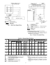
High-Pressure Switches — Switches have fixed,
nonadjustable settings. Switches are mounted on the
compressors.
Low-Pressure Switches — Switches have fixed,
nonadjustable settings. Switches are mounted on the
compressors.
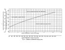
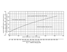
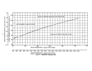
TO CHECK — Slowly close liquid shutoff valve and allow
compressor to pump down. Do not allow compressor
pump-down below 2 psig (13.8 kPa). Compressor should shut
down when suction pressure drops to cutout pressure in
Tables 1A-1D, and should restart when pressure builds up to
cut-in pressure shown.
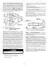
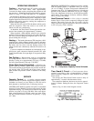
Outdoor Fans — Each fan is supported by a formed-
wire mount bolted to the fan deck and covered with a wire
guard. The exposed end of the motor shaft is covered with
a rubber boot. In case a fan motor must be repaired or re-
placed, be sure the rubber boot is put back on when the fan
is reinstalled and be sure the fan guard is in place before
starting the unit. Figure 15 shows the proper position of the
mounted fan. Fan motors have permanently lubricated
bearings.
Lubrication
FAN MOTORS have sealed bearings. No provisions are made
for lubrication.
COMPRESSOR has its own oil supply. Loss of oil due to a
leak in the system should be the only reason for adding oil
after the system has been in operation. See Preliminary Oil
Charge section.
Cleaning Coils — The coils can becleaned with a vacuum
cleaner, washed out with low velocity water, blown out with
low-pressure compressed air, or brushed (do not use wire
brush). Fan motors are drip-proof but not waterproof. Do
NOT use acid cleaners.
Clean outdoor coil annually or as required by location or
outdoor air conditions. Inspect coil monthly, and clean as
required. Fins are not continuous through coil sections; dirt
and debris may pass through first section, become trapped
between the 2 rows of fins (38AKS013) or 3 rows of fins
(38AKS014-024) and restrict outdoor airflow. Use a flash-
light to determine if dirt or debris has collected between coil
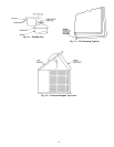
sections. Clean coil as follows:
1. Turn off unit power.
2. Remove screws holding rear corner posts and top
cover in place. Pivot top cover up 12 to 18 in. (305 to
457 mm) and support with a rigid support. See Fig. 16.
3. Remove clips securing tube sheets together at the return
bend end of the coil. Carefully spread the ends of the coil
rows apart by moving the outer sections. See Fig. 17.
4. Using a water hose, or other suitableequipment, flush down
between the sections of coil to remove dirt and debris.
5. Clean the remaining surfaces in the normal manner.
6. Reposition outer coil sections.
7. Reinstall clips which secure tube sheets.
8. Replace top cover and rear corner posts.
18