


OPERATING SEQUENCE
Cooling —
When the first stage (TC1) of the cooling ther-
mostat closes, the timer starts. After approximately
3 seconds, the timer expires, energizing the compressor and
fan motor no. 1. When the liquid pressure builds to approxi-
mately 257 psig (1772 kPa), fan motor no. 2 is energized.
On demand for additional cooling capacity, the second stage
(TC2) of the cooling thermostat closes, energizing a field-
supplied liquid line solenoid (LLS) valve, which opens. This
increases the suction pressure, causing the compressor to
operate at higher capacity.
When fan switch is set atAUTO, the indoor unit fan cycles
with the compressor. When the switch is set at ON, the
indoor unit fan runs continuously.
At shutdown, the Time Guard II timer prevents the com-
pressor from restarting for approximately 5 minutes.
When installed, a field-supplied solenoid valve (wired in
parallel with the compressor contactor coil), shuts off the liq-
uid line to prevent refrigerant migration back to the com-
pressor during the off cycle.
Heating — The heating thermostat (TH) energizes a field-
supplied relay which operates heating controls and ener-
gizes the indoor unit relay.When the fan switch is setat AUTO,
the indoor unit fan cycles with the heating control. The
indoor unit fan runs continuously when the fan switch is set
at ON.
Causes of complete unit shutdown are: interruption of sup-
plied power, open compressor internal protector (IP), open
control circuit breaker, or an open high- or low-pressure safety
switch.
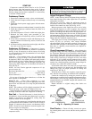
Fan Cycling — Head pressure control is accomplished
by cycling the fans. The no. 2 fan responds to liquid line
pressure, cycling on at approximately 255 psig (1758 kPa)
and off at approximately 160 psig (1103 kPa).
Winter Start Control (If Installed) — When the com-
pressor starts, the control’s bypass timer contacts close for
150 seconds, thereby bypassing the low-pressure switch dur-
ing start-up. After 150 seconds, the bypass timer contacts
open and the low-pressure switch is restored to the safety
circuit.
SERVICE
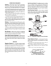
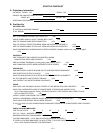
Capacity Control —
A suction pressure-actuated
unloader controls 2 cylinders and provides capacity control.
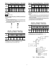
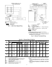
Unloaders are factory set (see Tables 1A-1D), but can be
field adjusted as described in the 2 following sections.
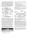
CONTROL SET POINT (cylinder load point) is adjustable
from 0 to 85 psig (586 kPa). To adjust, turn control set point
adjustment nut (Fig. 13) clockwise to its bottom stop. In this
position, set point is 85 psig (586 kPa). Next, turn adjust-
ment counterclockwise to desired control set point. Every
full turn counterclockwise decreases set point by 7.5 psig
(51.7 kPa).
PRESSURE DIFFERENTIAL (difference between cylinder
load and unload points) is adjustable from 6 to 22 psig
(41.4 to 152 kPag). To adjust, turn pressure differential ad-
justment screw (Fig. 13) counterclockwise to its back stop
position. In this position, differential is 6 psig (41.4 kPag).
Next, turn adjustment clockwise to desired pressure differ-
ential setting. Every full turn clockwise increases differen-
tial by 1.5 psig (10.3 kPag).
Head Pressure Control — Fan cycling is a standard
feature. The no. 2 fan cycles in response to changes in liquid
pressure. The switch cycles the fan off at 160 ± 10 psig
(1103 ± 69 kPa) as pressure decreases, and cycles it back on
at 255 ± 10 psig (1758 ± 69 kPa).
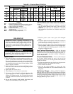
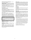
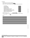
Time Guard II Circuit — Circuit prevents short-
cycling by providing a delay of approximately 5 minutes
before restarting compressor after shutdown from safety
device action.
On start-up, the Time Guard II timer causes a delay of
approximately 3 seconds after thermostat closes.
On compressor shutdown, the timer recycles for approxi-
mately 5 minutes. During this time, the compressor cannot
restart.
Refer to Fig. 14 and to label diagram on unit.
Fig. 13 — Compressor Capacity Control Unloader
Fig. 14 — Timer Sequence Chart
17