


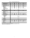

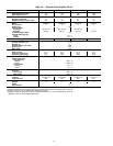
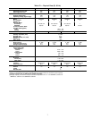
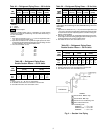

Table 6B — Electrical Data (3 Ph/50 Hz)
UNIT
38AKS
UNIT COMPR FAN MOTORS 230 v (Single Phase)
Model
Volts
MCA ICF
MOCP
(Fuse
Only)
RLA LRA
Total
Fans
FLA (ea)
Fan No.
kW
Nameplate
Supplied*
Min Max 1 2
013
803 230 198 264 47.5 134 75 32.9 128
2 2.9 3.5 1.20
903 400 342 457 31.4 80 50 20.0 74
014
803 230 198 264 51.0 149 75 35.7 143
2 2.9 3.5 1.20
903 400 342 457 34.0 89 50 22.1 83
016
803 230 198 264 66.9 206 100 47.9 200
2 2.9 3.5 1.20
903 400 342 457 43.0 121 60 29.3 115
024
803 230 198 254 91.8 213 150 67.9 207
2 2.9 3.5 1.20303 346 311 380 51.5 121 80 33.3 115
903 400 342 440 50.2 179 80 34.6 173
LEGEND
FLA — Full Load Amps (Fan Motors)
ICF — Maximum Instantaneous Current Flow during start-up
(LRA of compressor plus total FLA of fan motors)
kW — Total Fan Motor Input (kilowatts)
LRA — Locked Rotor Amps
MCA — Minimum Circuit Amps per NEC (U.S.A.),
Section 430-24
MOCP — Maximum Overcurrent Protection (amps)
RLA — Rated Load Amps (Compressor)
*Units are suitable for use on electrical systems where voltage sup-
plied to the unit terminals is not below or above the listed limits.
NOTES:
1. The MCA and MOCP values are calculated in accordance
with the National Electrical Code (NEC) article 440 (U.S.A.
standard).
2. Motor RLA and LRA values are established in accordance
with Underwriters’ Laboratories (UL) Standard 1995 (U.S.A.
standard).
PRE-START-UP
IMPORTANT: Before beginning Pre-Start-Up or
Start-Up, review Start-Up Checklist at the back of this
book. The Checklist assures proper start-up of a unit
and provides a record of unit condition, application re-
quirements, system information, and operation at ini-
tial start-up.
Do not attempt to start the condensing unit, even
momentarily, until the following steps have been com-
pleted. Compressor damage may result.
System Check
1. Check all air handler(s) and other equipmentauxiliary com-
ponents. Consult the manufacturer’s instructions regard-
ing any other equipment connected to the condensing unit.
If unit has field-installed accessories, be sure all are prop-
erly installed and correctly wired. If used, airflow switch
must be properly installed.
2. Backseat (open) compressor suction and discharge valves.
Now close valves one turn to allow refrigerant pressure
to reach test gages.
3. Open liquid line service valve.
4. Check tightness of all electrical connections.
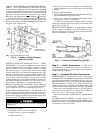
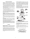
5. Compressor oil level should be visible in sight glass. See
Fig. 9. Adjust the oil level as required. Refer to Pre-
liminary Oil Charge section. No oil should be removed
unless the crankcase heater has been energized for at least
24 hours.
6. Be sure unit is properly leak checked, dehydrated, and
charged. See Preliminary Charge, this page.
7. Electrical power source must agree with nameplate
rating.
8. Crankcase heater must be firmly locked into compressor
crankcase. Be sure crankcase is warm (heater must be on
for 24 hours before starting compressor).
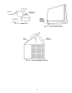
9. Be sure compressor floats freely on the mounting springs
and that snubber washers can be moved with finger pres-
sure. See Compressor Mounting, page 8, and Fig. 3 for
loosening compressor bolts.
Leak Test and Dehydration — Leak test the entire
refrigerant system using soap bubbles and/or an electronic
leak detector. Evacuate and dehydrate entire refrigerant sys-
tem by use of methods described in GTAC II, Module 4,
System Dehydration.
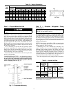
Turn On Crankcase Heater — Turn on crankcaseheater
for 24 hours before starting the unit to be sure all the
refrigerant is out of the oil. To energize the crankcase heater,
proceed as follows:
1. Set the space thermostat set point above the space tem-
perature so there is no demand for cooling.
2. Close the field disconnect.
3. Turn the fan circuit breaker on. Leave the com-
pressor circuit breakers off. The crankcase heater is now
energized.
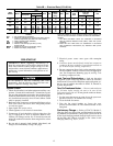
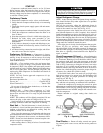
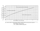
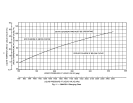
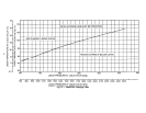
Preliminary Charge — Refer to GTAC II, Module 5,
Charging, Recovery, Recycling, and Reclamation for charg-
ing methods and procedures. Charge each system with R-22
by the liquid charging method (through liquid service valve)
on the high side. Charge according to the values in the
Charging Chart, Fig. 10, 11, or 12.
12