


START-UP
Compressor crankcase heater must be on for 24 hours
before start-up. After the heater has been on for 24 hours,
the unit can be started. If no time has elapsed since the pre-
liminary charge step has been completed, it is unnecessary
to wait the 24-hour period.
Preliminary Checks
1. Ensure that compressor service valves are backseated.
2. Verify that each compressor floats freely on its mounting
springs.
3. Check that electric power supply agrees with unit name-
plate data.
4. Verify that compressor crankcase heater is securely in place.
5. Check that compressor crankcase heater has been on at
least 24 hours.
6. Note that compressor oil level is visible in the sight glass.
7. Recheck for leaks using same procedure as pre-
viously outlined in Pre-Start-Up section, Leak Test and
Dehydration.
8. If any leaks are detected, evacuate and dehydrate as pre-
viously outlined in Pre-Start-Up section, Leak Test and
Dehydration.
9. All internal wiring connections must be tight, and all bar-
riers and covers must be in place.
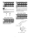
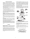
Preliminary Oil Charge — Compressor is factory
charged with oil (see Tables 1A-1D). When oil is checked at
start-up, it may be necessary to add or remove oil to bring
it to the proper level. One recommended oil level adjust-
ment method follows:
ADD OIL — Close suction service valve and pump down
crankcase to 2 psig (14 kPag). (Low-pressure switch must
be jumpered.) Wait a few minutes and repeat until pressure
remains steady at 2 psig (14 kPag). Remove oil fill plug above
the oil level sight glass, add oil through plug hole, and
replace plug. Run compressor for 20 minutes and check oil
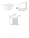
level. See Fig. 9.
NOTE: Use only Carrier approved compressor oil. Ap-
proved sources are:
Petroleum Specialties Inc. ................Cryol 150A
Texaco, Inc. .........................Capella WF-32
Witco Chemical Co. .....................Suniso 3GS
Do not use oil that has been drained out, or oil that has
been exposed to atmosphere.
REMOVE OIL — Pump down compressor to 2 psig
(14 kPag). Loosen the
1
⁄
4
-in. (6.4 mm) pipe plug at the com-
pressor base and allow the oil to seep out past the threads
of the plug.
NOTE: The crankcase will be slightly pressurized. Do not
remove the plug, or the entire oil charge will be lost.
Small amounts of oil can be removed through the oil pump
discharge connection while the compressor is running.
Start Unit — The field disconnect is closed, the fan cir-
cuit breaker is closed, and the space thermostat is set above
ambient so that there is no demand for cooling. Only the
crankcase heater will be energized.
Next, close the compressor circuit breaker and then reset
space thermostat below ambient so that a call for cooling is
ensured. If compressor does not start, set thermostat lower.
NOTE: Do not use circuit breaker to start and stop the com-
pressor except in an emergency.
After starting, there is a delay of at least 3 seconds before
compressor starts.
Never charge liquid into the low-pressure side of sys-
tem. Do not overcharge. During charging or removal of
refrigerant, be sure indoor-fan system is operating.
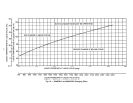
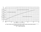
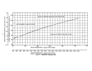
Adjust Refrigerant Charge
NOTE: Actual start-up and all refrigerant charge modifica-
tions should be done only under supervision of a qualified
refrigeration mechanic.
With all fans operating, adjust the refrigerant charge in
accordance with the unit charging charts located on the
inside of the control box doors and in Fig. 10-12.
Measure pressure at the liquid line service valve, being
sure Schrader depressor is used if required. Also, measure
liquid line temperature as close to the liquid service valve as
possible. Add charge until the pressure and temperature con-
ditions of the charging chart curve are met. If liquid pressure
and temperature point fall above curve, add charge. If liquid
pressure and temperature point fall below curve, reduce the
charge until the conditions match the curve.
If the sight glass is cloudy, check refrigerant charge again.
Ensure all fans are operating. Also ensure maximum
allowable liquid lift has not been exceeded. If charged per
chart and if the sight glass is still cloudy, check for a plugged
filter drier or a partially closed solenoid valve. Replace or
repair, as needed.
Check Compressor Oil Level — After adjusting the
refrigerant charge, allow the compressor to run fully loaded
for 20 minutes. Running oil level should be within view of
the crankcase sight glass. Stop the compressor at the field
power supply disconnect and check the crankcase oil level.
Add oil only if necessary to bring the oil into view in the
sight glass. If oil is added, run the compressor for an addi-
tional 10 minutes, then stop and check oil level. If the level
remains low, check the piping system for proper design for
oil return; also, check the system for leaks.
If the initial check shows too much oil (too high in the
sight glass) remove oil to proper level. See Preliminary Oil
Charge, this page, for proper procedure for adding and
removing oil. See Fig. 9.
When the above checks are complete, repeat the proce-
dure with the unit operating at minimum load conditions.
Unload the compressor by turning the control set point
adjustment nut counterclockwise until theadjustment nut stops.
The unloader is now at 0 psig (0 kPag) set point. If electric
actuated unloaders are installed, energize the solenoid to un-
load the compressor.
Return unloader to original setting after checks are
complete.
Final Checks — Ensure all safety controls are operat-
ing, control panel covers are on, and the service panels are
in place.
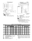
38AKS024 38AKS013,014,016
(06E COMPRESSOR) (06D COMPRESSOR)
Fig. 9 — Operating Oil Levels
13