


5
3 - HARDWARE DESCRIPTION
3.1 - General
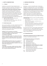
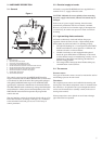
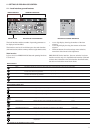
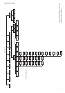
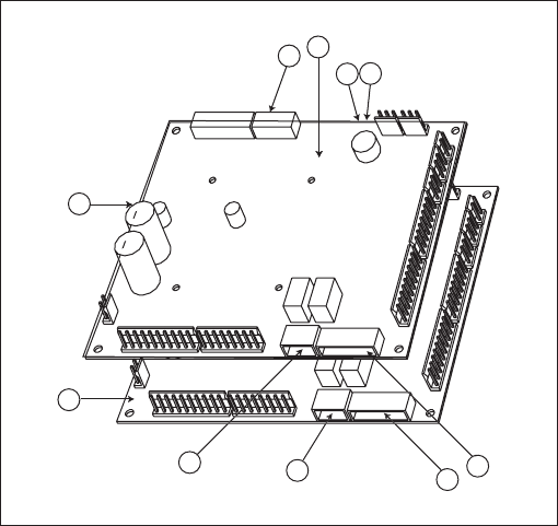
Figure 1
3.2 - Electrical supply to boards
All boards, except the PD-RCPM board, are supplied from a
common 24 V a.c. supply referred to earth.
CAUTION: Maintain the correct polarity when connecting
the power supply to the boards, otherwise the boards may be
damaged.
In the event of a power supply interrupt, the unit restarts
automatically without the need for an external command.
However, any faults active when the supply is interrupted are
saved and may in certain cases prevent a circuit or unit from
restarting.
3.3 - Light emitting diodes on boards
All boards continuously check and indicate the proper
operation of their electronic circuits. A light emitting diode
(LED) lights on each board when it is operating properly.
• The red LED flashing for a 2 second period on the NRCP-
BASE board indicates correct operation. A different rate
indicates a board or a software failure.
• On dual-circuit units or units equipped with optional
board, the green LED flashes continuously on all boards
to show that the board is communicating correctly over its
internal bus. If the LED is not flashing, this indicates a
SIO bus wiring problem.
• The orange LED of the master board flashes during any
communication via the CCN bus.
3.4 - The sensors
Pressure sensors
Two types of electronic sensors are used to measure the suction
and discharge pressure in each circuit.
Thermistors
The evaporator water sensors are installed in the entering and
leaving side. The outdoor temperature sensor is mounted below
the control box. An optional water system temperature sensor
can be used for master/slave assembly control (in the case of
leaving water control).
In heat pump units a sensor placed on an air heat exchanger
pipe ensures defrost operation.
Legend
1 CCN connector
2 Red LED, status of the board
3 Green LED, communication bus SIO
4 Orange LED, communication bus CCN
5 Remote master board customer control connection contacts
6 Remote slave board customer control connection contacts
7 Master board customer connection relay outputs
8 Slave board customer connection relay outputs
9 Master NRCP basic board
10 Slave NRCP basic board
The control system consists of an NRCP-BASE board for
single-circuit units and two NRCP-BASE boards (a master and
a slave board) for dual-circuit units. Heat pump units equipped
with optional additional heater stages use an additional board,
type PD-AUX. All boards communicate via an internal SIO bus.
The NRCP-BASE boards continuously manage the information
received from the various pressure and temperature probes. The
NRCP-BASE master board incorporates the program that
controls the unit.
The user interface consists of two display blocks with up to 26
LEDs and 16 buttons (according to unit type). It is connected
to the main basic board and gives access to a full array of
control parameters.
5
6
7
8
9
10
3
1
4
2
3