


7
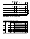
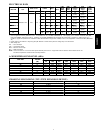
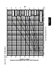
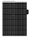
ELECTRICAL DATA
UNIT SIZE V/PH
OPER VOLTS* COMPR FAN
MCA
MIN
WIRE
SIZE†
MIN
WIRE
SIZE†
MAX
LENGTH
ft.(m)‡
MAX
LENGTH
ft.(m)‡
MAX
FUSE**
or BRK
AMPS
MAX MIN LRA RLA FLA 60˚ C 75 ˚ C 60˚ C 75˚ C
18
208/230/1---60 253 197
41 9.8 0.5 12.7 14 14
124
(37.80)
118
(35.97)
20
24 54 15.13 0.7 19.6 14 14
80
(23.16)
76
(23.16)
30
30 72.5 13.50 1.2 18.6 14 14
85
(25.91)
81
(24.69)
30
36 88 18.68 0.9 24.2 12 12
103
(31.39)
98
(29.87)
40
42 104 17.90 0.9 24.0 12 12
104
(31.70)
99
(30.18)
40
48 137 22.22 1.2 29.0 10 10
138
(42.06)
131
(39.93)
50
60 148 28.85 1.2 37.3 8 8
167
(50.90)
159
(48.46)
60
* Permissible limits of the voltage range at which the unit will operate satisfactorily
{ If wire is applied at ambient greater than 30° C , consult table 310--- 16 of the NEC (ANSI/NFPA 70). The ampacity of n o n---metall ic---shea th ed cable (NM),
trade name ROMEX, shall be that of 60° C conditions, per the NEC ( ANSI/NFPA 70) Article 336---26. If oth er th a n uncoated (n o---plated), 60 or 75° C
insulation, copper wire (solid wire for 10 AWG or smaller, stranded wire for larger than 10 AWG) is used, consult applicable tables of the NEC (ANSI/NFP A
70).
} Length shown is as measured 1 way along wire path between unit and service panel for voltage drop not to exceed 2%.
** Time ---Delay fuse.
FLA --- Full Load Amps
LRA --- Locked Rotor Amps
MCA--- Minimum Circuit Amps
RLA --- Rated Load Amps
NOTE: Control circuit is 24---V on all units and requires external power source. Copper wire must be used from service disconnect to unit.
All motors/compressors contain internal overload protection.
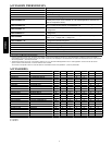
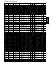
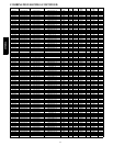
A--WEIGHTED S OUND LEVEL (dBA)
UNIT SIZE
STANDARD
RATING
(dB)
TYPICAL OCTAVE BAND SPECTRUM (dB, without tone adjustment)
125 250 500 1000 2000 4000 8000
18 71 55 58 64.5 65 64.5 63 55.5
24 74 57.0 62.5 68.5 69.5 67.5 63.0 55.0
30 73 58.0 66.0 66.0 67.5 64.5 61.0 54.5
36 74 53.5 65.5 64.5 68.5 66.0 62.0 54.5
42 74 59.0 62.0 66.0 69.0 65.0 60.0 51.5
48 75 54.5 61.0 66.0 71.0 65.5 62.0 56.5
60 75 56.5 66.5 67.5 69.5 67.5 63.5 56.5
NOTE: Tested in accordance with ARI Standard 270---95. (Not listed with ARI).
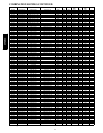
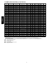
CHARGING SUBCOOLING (TXV--TYPE EXPANSION DEVICE)
UNIT SIZE---SERIES REQUIRED SUBCOOLING _F(_C) Hea ting Piston Size
18 10 (5.6) 42
24 10 (5.6) 52
30 10 (5.6) 57
36 10 (5.6) 57
42 10 (5.6) 67
48 9 (5.0) 67
60 10 (5.6) 78
25HCS3C