


LIQUID LIFT — Amount of liquid lift available before re-
frigerant flashing occurs depends on amount of liquid sub-
cooling in the system.
All 09BY condensers have positive subcooling when ap-
plied with optimum charge. With subcooling, it is possible
to overcome an appreciable pressure drop and/or static head
pressure (due to elevation of the liquid metering device above
the condenser when condenser is below evaporator coil).
When 09BY condensers are applied with minimum charge,
they do not provide positive subcooling. If subcooling is re-
quired, it must be obtained by external means such as a liq-
uid suction interchanger.
It is recommended that the evaporator be either at the same
level as the condenser or lower than the condenser when mini-
mum is used.
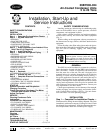
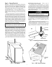
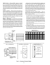
SWEAT CONNECTIONS — Connections are made inside
the unit, and piping may enter from either side. For ease in
brazing, it is recommended that all internal solder joints be
made before unit is placed in its final position. See 50BZ (or
other compressor-bearing unit) base unit installation instruc-
tions for proper line sizing and piping procedures.
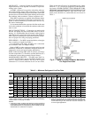
FIELD PIPING — For 09BY remote installation, select pipe
sizes according to length from Table 3.
Use refrigerant grade piping. If tubing size is other than
unit connection sizes, use adapter fittings.
Refer to 50BZ (or other compressor-bearing unit) base unit
installation instructions to determine refrigerant charge ad-
justment for remote and special piping applications.
NOTE: When installing 09BY units in systems, add charge
for other components (i.e., filter drier, moisture indicator, etc.)
to determine system charge quantity. Record charge.
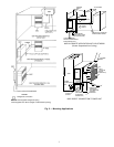
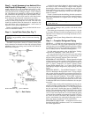
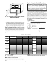
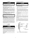
MANIFOLDING CIRCUITS — The 09BY units with 2 or
3 circuits (012-024 units) may be manifolded together to be
used as a single-circuit condenser. See Fig. 8 for a typical
connection of a 2-circuit condenser for use on one circuit.
Three-circuit units (024) may be manifolded in any combi-
nation of 1, 2, or 3 circuits per compressor. When manifold-
ing circuits, NEVER CONNECT TWO SEPARATE COM-
PRESSOR EVAPORATOR CIRCUITSTOGETHER ON THE
SAME CONDENSER CIRCUIT. Pipe sizes for the com-
bined circuit should be no smaller than the sizes shown in
Table 3.
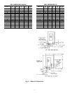
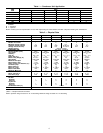
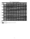
Table 3 — Minimum Refrigerant Line Size Data
UNIT
09BY
LENGTH OF PIPE
0TO15FT 16TO25FT 26TO50FT 51TO75FT 76TO100FT
Qty
Hot Gas
Line
(in.)
Liquid
Line
(in.)
Qty
Hot Gas
Line
(in.)
Liquid
Line
(in.)
Qty
Hot Gas
Line
(in.)
Liquid
Line
(in.)
Qty
Hot Gas
Line
(in.)
Liquid
Line
(in.)
Qty
Hot Gas
Line
(in.)
Liquid
Line
(in.)
006 1
1
⁄
2
1
⁄
2
1
5
⁄
8
1
⁄
2
1
7
⁄
8
1
⁄
2
1
7
⁄
8
1
⁄
2
1
7
⁄
8
1
⁄
2
008 1
1
⁄
2
1
⁄
2
1
7
⁄
8
1
⁄
2
1
7
⁄
8
1
⁄
2
1
7
⁄
8
1
⁄
2
1
7
⁄
8
5
⁄
8
012*
2
1
⁄
2
1
⁄
2
2
5
⁄
8
1
⁄
2
2
7
⁄
8
1
⁄
2
2
7
⁄
8
1
⁄
2
2
7
⁄
8
1
⁄
2
1
7
⁄
8
1
⁄
2
1
7
⁄
8
1
⁄
2
11
1
⁄
8
5
⁄
8
11
1
⁄
8
5
⁄
8
11
1
⁄
8
5
⁄
8
014*
2
1
⁄
2
1
⁄
2
2
7
⁄
8
1
⁄
2
2
7
⁄
8
1
⁄
2
2
7
⁄
8
1
⁄
2
2
7
⁄
8
5
⁄
8
1
7
⁄
8
1
⁄
2
1
7
⁄
8
5
⁄
8
11
1
⁄
8
5
⁄
8
11
1
⁄
8
5
⁄
8
11
1
⁄
8
7
⁄
8
016*
2
1
⁄
2
1
⁄
2
2
7
⁄
8
1
⁄
2
2
7
⁄
8
1
⁄
2
2
7
⁄
8
1
⁄
2
2
7
⁄
8
5
⁄
8
11
1
⁄
8
5
⁄
8
11
1
⁄
8
5
⁄
8
11
1
⁄
8
5
⁄
8
11
1
⁄
8
7
⁄
8
11
3
⁄
8
7
⁄
8
024*
2or3
1
⁄
2
1
⁄
2
2or3
7
⁄
8
1
⁄
2
2or3
7
⁄
8
1
⁄
2
2or3
7
⁄
8
1
⁄
2
2or3
7
⁄
8
5
⁄
8
11
1
⁄
8
5
⁄
8
11
1
⁄
8
5
⁄
8
11
1
⁄
8
7
⁄
8
11
3
⁄
8
7
⁄
8
11
3
⁄
8
7
⁄
8
*Circuits may be manifolded to a single compressor. Multiple con-
denser circuits should be on the same evaporator. See Manifolding
Circuits section on this page for details.
NOTES:
1. A standard number of elbows and fittings have been considered
in sizingpiping(approximately 20%loss).Special applicationsmay
require different minimum refrigerantline sizes.Contact yourlocal
representative for assistance as required.
2. Line sizes are in inches.
3. A hot gas line check valve is recommended when the 09BY con-
denser is installed above the compressor. Pressure loss through
recommended hot gas line check valve has been included in 16
to 100 ft length applications.
Fig.8—Typical 2-Circuit Condenser Manifolded
For Single-Circuit Use
9