


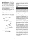
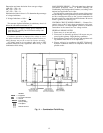

CHECK VALVE — When the 09BY condenser is installed
with the condenser located above the compressor evapora-
tor, it is recommended that a field-supplied check valve be
installed on the hot gas discharge line. This prevents refrig-
erant which condenses in the discharge line during the off
cycle from draining back into the compressor. Install the check
valve at the compressor line before the line goes up to the
condenser. Check valve part no. EC37BP183 or similar may
be used.
SERVICE VALVES — Service valves are not factory in-
stalled on the 09BY units. If isolation of the refrigerant charge
in the condenser from the unit or the piping system is de-
sired, it is recommended that field-supplied service valves
be installed in the discharge and liquid line inside the 09BY
condenser. A Schrader port connection is also recommended
on the liquid and discharge line at the condenser for ease in
troubleshooting when the condenser is located out of sight
from the compressor evaporator unit.
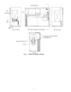
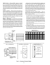
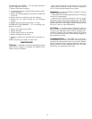
Step 6 — Ductwork — The 09BY unit is designed for
use either with or without ductwork or rain louvers. If either
is used, care must be taken to eliminate air recirculation. Re-
circulation can be minimized by blocking the front dis-
charge and discharging through an extension elbow. When
properly designed, hinged discharge louvers can be applied
to ductwork and to the condenser air discharge. Fixed rain
louvers over discharge outlets can cause excessive recircu-
lation and nuisance high-pressure switch cutouts. Obstruc-
tions closer than 10 ft to the discharge air pattern can cause
significant recirculation. See Fig. 9 for ductwork installation
to prevent recirculation of air.
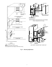
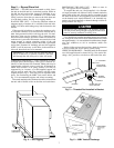
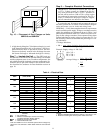
If ductwork is used from standard discharge openings and
another bird screen isprovided, remove factory-supplied screen
to reduce static pressure loss. Units 09BY006-014 have a
factory-installed flange to connect ductwork to the con-
denser air inlet. Units 09BY016 and 024 are provided with
flanges taped inside the unit for shipping. To attach the duct
to the unit inlet, mount the flange by removing the screws
that hold the condenser coil. Insert the flange and replace the
screws. See Fig. 10. Take care not to puncture the coil when
removing and installing screws.
CONDENSER AIR DUCT INSULATION — The con-
denser air duct must be insulated on indoor installations to
prevent moisture condensation on the unit panels during cold
weather. Insulate as follows:
1. If metal ductwork is used, insulation may be applied on
the inside of the duct. This installation should be ex-
tended to cover the inside of the 09BY duct flanges.
It is necessary to insulate the inside of the ducts at the
duct flanges to reduce heat loss from the metal cabinet by
conduction through the duct flanges and into the cold duct.
Interior insulation allows the metal duct to approach room
temperature. It also prevents condensation from forming
and collecting under the insulation which will occur with
exterior duct insulation.
NOTE: Fiberglass duct board may also be used if per-
mitted by local codes.
2. If insulation is applied to the outside of the metal duct,
the inside must be insulated for a length of 10 in. from
the unit (including the duct flanges) or up to the flexible
duct vapor barrier on the outside, which must be tightly
sealed to prevent condensation under the insulation.
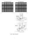
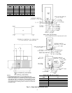
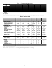
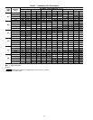
DIMENSIONS (in.)
UNIT
09BY
ABCD E F G
006 24 11
1
⁄
8
617
1
⁄
8
16
1
⁄
8
22
3
⁄
8
41
1
⁄
8
008 24 14 6 20 16
1
⁄
8
26
7
⁄
8
48
1
⁄
4
012 24 14 6 20 16
1
⁄
8
26
7
⁄
8
55
5
⁄
8
014 30 14 6 20 30
3
⁄
8
26
7
⁄
8
63
1
⁄
4
016 30 20 6 26 30
3
⁄
8
36
3
⁄
8
85
9
⁄
16
024 30 20 6 26 30
3
⁄
8
36
7
⁄
8
85
7
⁄
16
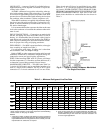
Fig. 9 — Condenser Ductwork Details
10