


Step 3 — Install Accessory Low-Ambient Kit or
Inlet Filter Kit (If Required) —
If the unit will be op-
erated with inlet air to the condenser below 50 F, a low-
ambient damper may be required. The low-ambient kit con-
trols head pressure by discharge dampers on the condenser
fan. The dampers are actuated by a refrigerant-operated pis-
ton connected to the discharge line of the condenser. If low-
ambient accessory will be used, install it at this time (before
final refrigerant and ductwork connections are made).
An accessory filter rack may also be installed on the con-
denser air inlet to help keep the coil clean. This filter rack
should be installed before the ductwork is attached to the
unit, and before unit is mounted against a wall louver (if
required in your specific application).
Refer to installation instructions provided with the acces-
sories for installation details.
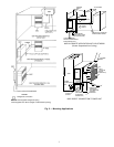
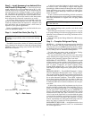
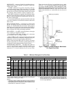
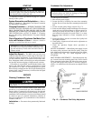
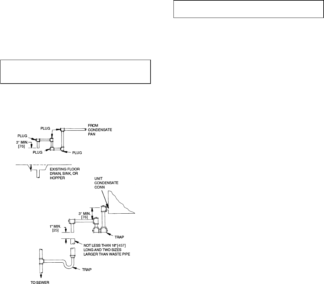
Step 4 — Install Rain Drain (See Fig. 7)
IMPORTANT: A rain drain connection MUST BE
USED if any possibility exists of rain water entering
the unit.
The 09BY unit provides a choice of 2 drain locations. Rain
drain connection can be made on either side of the unit. Block
whichever drain is not being used, but DO NOT BLOCK
BOTH drain locations.
A drain kit is provided (shipped in the fan section). This
kit consists of PVC drain fittings to adapt to field-supplied
threaded pipe. Make connections through the unit side panel.
Some applications may require connection to either galva-
nized steel or copper drain pipe; consult local code require-
ments for details.
If unit is located inside the building, the drain connection
near the refrigerant piping can be used for external drainage.
Run drain connection to a trapped drain, and plug unused
connection.
IMPORTANT: NEVER use pipe smaller than
3
⁄
4
in.
in the drain run.
For vertical discharge units, provide a rain drain on the
back of the unit.
Pitch drain pipe downward at a slope of at least
1
⁄
4
-in. per
ft for proper drainage. Provide tees plugged on one side for
cleanouts. Leave clearance for servicing, and observe all lo-
cal sanitary codes.
Refer to Carrier System Design Manual for additional pip-
ing details.
Step 5 — Complete Refrigerant Piping
GENERAL — All field leak and pressure testing should be
done in accordance with local code requirements. If a local
code does not exist, useASHRAE (American Society of Heat-
ing, Refrigeration and Air Conditioning Engineers) Stand-
ard 15, Safety Code for Mechanical Refrigeration.
For leak testing procedures, refer to the Carrier ‘‘Refrig-
erant Service Techniques’’ book, Form SFT-01.
For any parts that need to be removed, use a mini tubing
cutter. Perform phos-copper brazing on all field-made con-
nections while protecting adjacent joints from heat.
REFRIGERANT LINE SIZING — Sizing depends on length
of lines between various sections of the refrigerant system.
Consider the amount of liquid lift and drop in the system as
well as proper compressor oil return. Consult Carrier
System Design Manual, Part 3, or Carrier E20-II Refrig-
erant Piping Computer Program for proper piping sizes and
design.
PRESSURE RELIEF — The ASHRAE Standard 15, Safety
Code for Mechanical Refrigeration states: ‘‘Every refriger-
ating system shall be protected by a pressure relief device or
some other means designed to safely relieve pressure due to
fire or other abnormal conditions.’’ Since 09BY condensers
do not have pressure relief devices, one must be field sup-
plied and installed either before the liquid line service valve
or inside the 09BYunit. Each circuit must have its own pres-
sure relief.
If desired, the pressure relief requirement can also be sat-
isfied by installing a fusible plug in the liquid line. To do so,
install a tee in the liquid line with a
1
⁄
4
-in. NPT fitting on the
tee side, and install a fusible plug (part no. EK02KK105 or
similar). The temperature rating of the fusible plug should
be between 205 F and 220 F (96 C and 104 C). If a service
valve is used on the liquid line, be sure that both the piping
system and the condenser are protected for relief if all serv-
ice valves are closed. Note that if the condenser is located
indoors, requirements for venting the fusible plug to the out-
doors may apply. Consult local code requirements.
REFRIGERANT RECEIVER —Arefrigerant receiver isnot
furnished with 09BY condensers and is not recommended
for normal applications.
NOTE: Dimensions in [ ] are in millimeters.
Fig. 7 — Rain Drains
8