


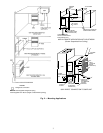
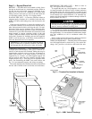
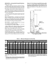
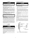
Step 2 — Rig and Place Unit
RIGGING — The 09BY units are mounted on skids. Leave
the unit on the skid until it is in the final position. While on
the skid, the unit can be rolled, dragged or forklifted; do not
apply force to the unit. Use a minimum of 3 rollers when
rolling, and raise from above to remove the skid when unit
is in the final position. See Fig. 4 for rigging details.
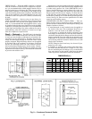
PLACING THE UNIT — Locate the condenser where an
adequate supply of outdoor air is available for the unit inlet.
NOTE: Unit inlet and discharge may both be ducted to the
outside.
Either provide inlet filters to protect the condenser coils,
or locate the condenser in an area free from airborne dirt or
other foreign material which could clog the coils. For mul-
tiple units, allow service clearance (Fig. 3) between units,
and locate unit discharges and inlets so that recirculation of
condenser air is prevented. Placement area must be level and
strong enough to support operating weight of the unit
(Table 2). Bolt unit securely in place when unit is positioned
and leveled. Fasteners for mounting unit are field supplied.
NOTE: It will be necessary to drill holes in the unit base or
side wall where bolts are to be mounted.
IMPORTANT: Use care if rain will enter the unit (if
unit is located fully or partially outdoors). DO NOT
drill through the unit drain pan or leaks will result.
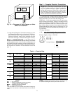
VIBRATION ISOLATION — Units mounted in or above
occupied spaces should employ some type of vibration iso-
lation. For units that are floor mounted, rubber pads may be
located under each unit corner or unit may be mounted on
rubber shear isolators or on spring isolators. Unit may be
supported by its 4 corners, or a field-supplied support rail
may be used for each side. Size isolators with the corner
weights shown in Fig. 3. Units may also be suspended from
above. See Positioning the 09BY Unit section below and
Fig. 5 for recommended support and isolator mounting.
Ductwork attached to the condenser should be isolated from
the unit with a flexible collar on the inlet and outlet ducts.
POSITIONING THE 09BY UNIT — Refer to notes in
Fig. 3 for typical service clearances.
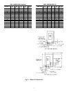
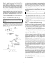
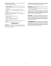
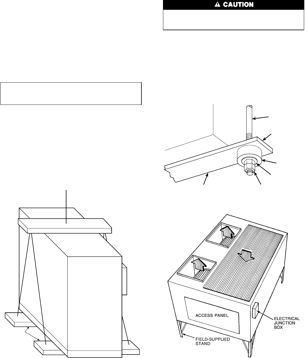
To suspend the unit, use 4, field-supplied,
1
⁄
2
-in. diameter
(or larger) threaded rods. Mount 2 heavy channels under the
entire width of the unit, allowing them to protrude beyond
the width of the unit so that supporting rods can be installed
on the channel ends. Attach minimum
1
⁄
2
-in. threaded sup-
porting rods (field-supplied) to channels through a rubber or
spring isolator. See. Fig. 5.
DO NOT use rods smaller than
1
⁄
2
-in. diameter. Smaller
rods may not be strong enough to support the unit. Rods
must be securely anchored in ceiling joists.
Use a double hex nut when attaching hanger rods to brack-
ets.A single nut could loosen from vibration of the unit. Pitch
unit approximately
1
⁄
4
-in. toward drainin both directions (length-
wise and widthwise) to aid in condensate and/or rain
removal.
Before sliding unit into final position, check for clearance
to access panels and service area to install piping.
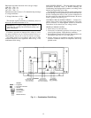
VERTICAL DISCHARGE— The 09BYunits can be mounted
on a field-supplied stand as shown in Fig. 6 for vertical dis-
charge. Also, provide a rain drain on the back of the unit.
SPREADER BAR
SUPPORTS
UNDER SKID
Fig. 4 — Unit Rigging
09BY
UNIT
BRACKET*
DOUBLE HEX NUT*
FIELD SUPPLIED
WASHER*
RUBBER
ISOLATOR*
PROTRUDING
CHANNEL END*
1/2" THREADED
ROD*
*Field supplied.
Fig. 5 — Threaded Rod Installed in Bracket
Fig. 6 — 09BY Vertical Discharge
7