


Determine maximum deviation from average voltage:
(AB) 243 – 239=4v
(BC) 239 – 236=3v
(AC) 239 – 238=1v
Maximum deviation is then 4 v. To determine the percentage
of voltage imbalance:
4
% Voltage Imbalance = 100 x
239
= 1.7%
This amount of phase imbalance is satisfactory since it is
below the allowable maximum of 2%.
IMPORTANT: If supply voltage phase imbalance is
more than 2%, contact your local electric utility com-
pany immediately.
Condenser operation on improper line voltage or exces-
sive phase imbalance may be considered abuse and any re-
sulting damage may not be covered by Carrier warranty.
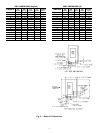
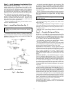
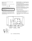
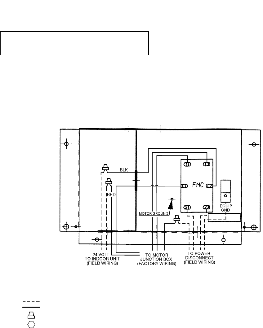
All wiring must be in accordance with local or NEC
(National Electrical Code) regulations. Refer to Fig. 11 for
combination field wiring.
MAIN POWER WIRING — The units must have adequate
overcurrent protection, fuses, or HACR (Heating, Air
Conditioning and Refrigeration) breakers, according to the
national and applicable local codes.
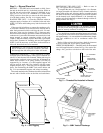
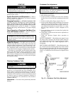
For field power connections, all main power wiring enters
the unit through a factory-punched access hole under the con-
trol box. Attach power wires to the 3 power connections in
the unit control box using field-supplied wirenuts. Be sure to
install a ground wire. See Fig. 11.
CONTROL CIRCUIT POWER WIRING — Connect 24-v
control wires to the 2 low-voltage connections at the com-
pressor contactor. Use field-supplied wirenuts to make the
connections in the control box low-voltage section.
GENERAL WIRING NOTES
1. Power entry is at one end only.
2. Fan motors are thermally protected. All motors are pro-
tected against primary single-phasing conditions.
3. Replacement of factory wires must be with appliance wir-
ing material rated 105 C or its equivalent.
4. Factory wiring is in accordance with NEC. Field modi-
fications or additions must be in compliance with all ap-
plicable codes.
LEGEND
EQUIP — Equipment
FMC — Fan Motor Contactor
GND — Ground
Field Wiring
Factory Wiring
Field Splice
Marked Terminal
Fig. 11 — Combination Field Wiring
12