71
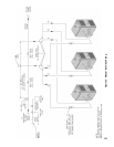
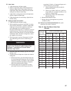
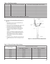
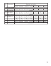
Table 11: Pilot Burner Location
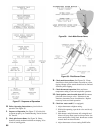
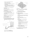
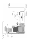
G. Procedure for Measuring Differential Pressure (See
Figure 43).
1. With boiler off, remove Gray and Black Hoses at
differential pressure switch.
2. With tees and ¼ inch aluminum stubs, connect water
manometer as shown with additional tubing.
3. Start boiler and read Pressure on Manometer
when boiler water temperature reaches operating
temperature. Refer to Table 12 for minimum
readings.
NOTE: If switch drops-out before boiler reaches
temperature or if pressure differential readings are
below minimums shown in Table 12, check for
cracks in hose or contact your nearest Burnham
representative.
4. Stop boiler, remove manometer and reconnect hoses
to differential pressure switch. See Figures 40 and
43.
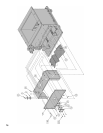
Figure 43: Differential Pressure Measurement
ledoMrelioBtekcarBtoliPhtiwrenruBniaM *srenruBniaMneewteBdetacoLrenruBtoliP
3-GCS2 3&2
4-GCS3 4&3
5-GCS4 5&4
6-GCS5 6&5
7-GCS6 7&6
8-GCS7 8&7
9-GCS8 9&8
.reliobfotnorfmorfdeweivsathgirottfelderebmunsrenrub
niaM*
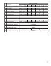
Table 12: Differential Pressure Switch Settings
ledoMrelioB
erusserPlaitnereffiDmuminiM
.tF999,4otleveLaeSnoitavelE.tF000,01-000,5
3-GCS.c.w"23.1.c.w"08.
4-GCS.c.w"71.1.c.w"56.
5-GCS.c.w"71.1.c.w"56.
6-GCS.c.w"88..c.w"53.
7-GCS.c.w"08..c.w"03.
8-G
CS.c.w"88..c.w"53.
9-GCS.c.w"88..c.w"53.


