


62
A. General Guidelines
1. Read and follow all venting, combustion air,
water piping, gas piping and electrical instructions
contained in this manual unless otherwise instructed
in this section.
2. Consult Local Building Codes or National Fuel Gas
Code, NFPA 54/ANSI Z222.3 for restrictions and
instructions on modular boiler installations.
B. Module Sizing
Burnham recommends sizing each boiler in a modular
system to provide 20 % of the combined heating load
where ever possible.
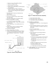
C. Venting
1. Each boiler must have an individual vent pipe.
Refer to Venting Section of this manual for venting
guidelines and options.
GNINRAW
.rehtegotsepiptnevdlofinamtonoD
2. The maximum vent length for each boiler is fi fty
(50) equivalent feet.
3. The minimum horizontal distance between vent
terminations is one (1) foot. Additional horizontal
distance is desirable to avoid frost damage to the
building. Vent terminations must be at least twelve
(12) inches above the ground plus the expected
snow accumulation.
NOITUAC
esolcsnoitanimrettnevelpitlumgnillatsnI
nopudliubtsorfsetomorprehtegot
,ytilibissopsihteziminimoT.sgnid
liub
ehtotgnidliubehtmorfecnatsidehtdnetxe
ehtesaercnidnanoitanimrettnevehtfodne
.snoitanimretneewtebecnatsidlatnoziroh
4. Multiple vertical vent pipes may be piped through
a common conduit or chase so that one roof
penetration may be made. Each vent termination
must be one (1) foot from other terminations.
D. Air Intake Piping
1. Each boiler must have an individual air intake pipe,
refer to Venting Section of this manual for Air Intake
Guidelines and Options.
2. The maximum air intake length for each boiler is
fi fty (50) equivalent feet.
3. Locate air intake termination on the same wall as
the vent termination if possible, to prevent nuisance
boiler shutdowns. However, boiler may be installed
with vertical venting and sidewall combustion air
inlet (or visa versa) if installation conditions do not
allow alternate arrangement.
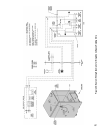
VII. Modular Installation
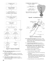
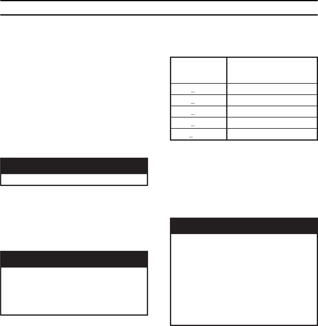
Table 9: Modular Boiler Water Manifold Sizing
E. Water Piping (See Table 9)
Installing a low water cutoff in the system piping of
modular systems is strongly recommended and may be
required by Local Codes.
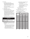
F. Gas Piping
1. Refer to National Fuel Gas Code, Local Codes and
Tables 7 and 8 for gas pipe sizing.
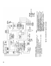
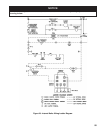
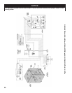
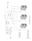
2. Each boiler must be piped as shown in Figure 27.
GNINRAW
evobasignidliubehtnierusserpsagfI
rotalugererusserpsaglanoitiddana,gisp½
rotalugerlanoitiddaenognisU.deriuqersi
efasnunitluseryamsreliobelpitlumrof
rotalugerlanoitiddaehT.noitareporeliob
sagetalugerylreporpo
telbaebtsum
.reliobtsellamsehtfotupniehttaerusserp
eromroowt,sihtodtonnacrotalugerehtfI
tlusnoC.deriuqererasrotalugerlanoitidda
saglacolro/dnarerutcafunamrotaluger
tnempiuqednasnoitcurtsnirofreilppus
.sgnitar
G. Electrical
1. Each boiler must be provided with a fused
disconnect and service switch.
2. Install wiring in accordance with requirements of
authority having jurisdiction. In the absence of such
requirements, follow the National Electric Code,
NFPA 70 and/or CSA C22.1 Electric Code.
H. Modular Boiler Control Systems
Contact a controls manufacturer such as Honeywell or
Tekmar to properly apply a modular control system.
Common systems may use outdoor temperature, return
water temperature or both to stage the boilers.
tuptuOdenibmoC
)HBM(
muminiMdednemmoceR
dlofinaMretaWnommoC
)TPN(eziS
< 661"¼1
< 062"½1
< 055"2
< 009"½2
< 0002"3