


64
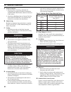
A. Safe operation and other performance criteria were
met with gas manifold and control assembly provided
on boiler when boiler underwent tests specifi ed in
American National Standard for Gas-Fired Low-
Pressure Steam and Hot Water Boilers, ANSI Z21.13.
B. Verify that the venting, water piping, gas piping and
electrical system are installed properly. Refer to
installation instructions contained in this manual.
C. Confi rm all electrical, water and gas supplies are
turned off at the source and that vent is clear of
obstructions.
D. Confi rm that all manual shut-off gas valves between
the boiler and gas source are closed.
GNINRAW
llawollofdnadnatsrednu,daeryletelpmoC
erofeblaunamsihtnisnoitcurtsni
.putratsgnitpmetta
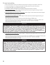
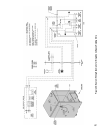
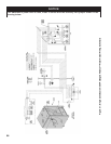
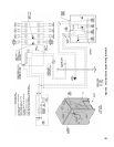
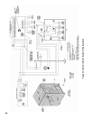
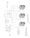
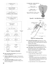
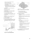
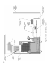
E. Fill entire heating system with water and vent air
from system. Use the following procedure on a Series
Loop or multi-zoned system installed as per Figure 25
or 26 to remove air from system when fi lling.
GNINRAW
sihtfoerusserpgnitarepomumixamehT
sihtdeecxereveN.gisp03sireliob
erusserpegnahcrogulptonoD.erusserp
.evl
avfeiler
ECITON
mretgnolamrofrepotderiuqersitifI
eht,metsyscinordyhehtfotseterusserp
adiovaotdetalosiebtsrifdluohsreliob
riafoepacseehtoteudssolerusserp
.reliobehtnideppart
tseterusserpmretgnolamrofrepoT
tsumriadeppartLLA,re
liobehtgnidulcni
.reliobehtmorfdevomerebtsrif
htiw,tsetahcusgniruderusserpfossolA
noitacidninasi,egakaelretawelbisivon
.riadeppartdeniatnocreliobehttaht
1. Close full port ball valve in boiler supply piping.
2. Isolate all zones by closing zone valves or shut-off
valves in supply and return of each zone(s).
3. Attach a hose to the vertical hose bib located prior to
the full port ball valve in the system supply piping.
(Note - Terminate hose in fi ve gallon bucket at a
suitable fl oor drain or outdoor area).
VIII. System Start-up
4. Starting with one circuit at a time, open zone valve
or shut-off valve in system supply and return piping.
5. Open hose bib.
6. Open fi ll valve (Make-up water line should be
located directly after full port ball valve in system
supply piping between air scoop and expansion
tank).
7. Allow water to overfl ow from bucket until discharge
from hose is bubble free for 30 seconds.
8. Close the opened zone valve or shut-off valve for
the zone being purged of air, then open the zone
valve or shut-off valve for the next zone to be
purged. Repeat this step until all zones have been
purged. At completion, open all zone valves or
shut-off valves.
9. Close hose bib, continue fi lling the system until the
pressure gauge reads 12 psi. Close fi ll valve.
(Note - If make-up water line is equipped with
pressure reducing valve, system will automatically
fi ll to 12 psi. Follow fi ll valve manufacturer’s
instructions).
10. Open isolation valve in boiler supply piping.
11. Remove hose from hose bib.
F. Confi rm that the boiler and system have no water
leaks.
G. Prepare to check operation.
1. Obtain gas heating value (in Btu per cubic foot)
from gas supplier.
2. Connect manometer to pressure tap on gas valve.
Use 1/8 NPT tapping provided.
3. Temporarily turn off all other gas-fi red appliances.
4. Turn on gas supply to the boiler gas piping.
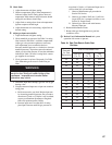
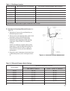
5. Confi rm that the supply pressure to the gas valve is
14 in. w.c. or less. Refer to Table 5 for minimum
supply pressure.
6. Open the fi eld installed manual gas shut-off valve
located upstream of the gas valve on the boiler.
7. Using soap solution, or similar non-combustible
solution, electronic leak detector or other approved
method. Check that boiler gas piping valves, and
all other components are leak free. Eliminate any
leaks.
REGNAD
semalfnepo,seldnac,sehctamesutonoD
.skaelrofkcehcotecruosnoitingirehtoro
8. Purge gas line of air.