


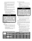

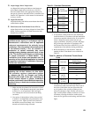
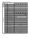
69
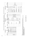
Boiler
Model
Gas
Valve
Size
(NPT)
(Dungs)
Gas Valve Model
Fuel Converted
Planned
Installation
Altitude
Range
From To
ALP080
1/2”
GB-WND 055 D01
S00 253082
Natural
Gas
LP 0 - 7,000 Ft.
ALP105
GB-WND 055 D01
S00 253083
ALP150
ALP210
GB-WND 055 D01
S00 253084
ALP285
3/4”
GB-WND 057 D01
S00 253085
ALP399
GB-WND 057 D01
S00 253086
3. If conversion is being made on a new installation,
install the boiler in accordance with the installation
instructions supplied with the boiler. If an installed
boiler is being converted, connect the new gas
supply to the boiler, check for gas leaks, and purge
the gas line up to the boiler in accordance with
the National Fuel Gas Code (ANSI Z223.1) or the
requirements of the authority having jurisdiction.
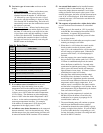
4. Before attempting to start the boiler, make the
number of turns to the throttle screw called for in
Table 22.
Table 22: Number of Clockwise Throttle Screw
Turns
Boiler Model Gas Valve
Throttle Screw Turns at
Altitude Range
0 - 7000 Ft.
ALP080
Dungs
GB-055
(½” NPT)
2¾
ALP105 4
ALP150 3¼
ALP210 4
ALP285
Dungs
GB-057
(¾” NPT)
4½
ALP399
Dungs
GB-057 HO
(¾” NPT)
1¾
5. Attempt to start the boiler using the lighting
instructions located inside the lower front cover of
the boiler. If the boiler does not light on the rst
try for ignition, allow to boiler to make at least
four more attempts to light. If boiler still does not
light, turn the throttle counter clockwise in 1/4 turn
increments, allowing the boiler to make at least
three tries for ignition at each setting, until the boiler
lights.
Table 21: Permitted Conversions
N. Adjust Supply Water Temperature
As shipped, the heating and indirect water heater set
point supply temperatures are both set to 180°F. If
necessary, adjust these to the appropriate settings for
the type of system to which this boiler is connected. See
Section XII “Operation” of this manual for information
on how to do this.
O. Adjust Thermostats
Adjust the heating and indirect water heater thermostats
to their nal set points.
P. Field Conversion From Natural Gas to LP Gas
Alpine Series boilers are factory shipped as Natural Gas
builds. Follow steps below for eld conversion from
Natural Gas to LP Gas.
WARNING
This conversion should be performed by a
qualied service agency in accordance with the
manufacturer’s instructions and all applicable
codes and requirements of the authority having
jurisdiction. If the information in these instructions
is not followed exactly, a re, an explosion or
production of carbon monoxide may result
causing property damage, personal injury, or loss
of life. The qualied service agency is responsible
for proper conversion of these boilers. The
conversion is not proper and complete until the
operation of the converted appliance is checked
as specied in the Alpine™ Installation, Operating
and Service Instructions.
WARNING
These instructions include a procedure for
adjusting the air-fuel mixture on this boiler.
This procedure requires a combustion analyzer
to measure the CO
2
(or Oxygen) and Carbon
Monoxide (CO) levels in ue gas. Adjusting the
air-fuel mixture without a proper combustion
analyzer could result in unreliable boiler operation,
personal injury, or death due to carbon monoxide
poisoning.
1. Make sure that the planned fuel conversion is listed
in Table 21. If the planned conversion is not shown
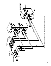
in Table 21, it is not permitted. Refer to Figure
34 to identify the valve used on the model being
converted.
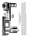
2.
Conversion of Alpine Series boilers from one fuel
to another is accomplished using the throttle screw
on the gas valve. Figure 48 shows the location of
the throttle screw on the Dungs valve. Locate the
throttle on the boiler being converted.