


18
7. Brace exterior piping if required.
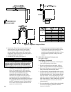
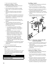
Combustion Air Piping - Vertical
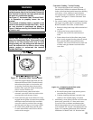
1. See Paragraph D for instructions on attaching the
vent system connector to the boiler.
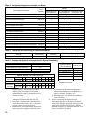
2. Do not exceed maximum combustion air length.
Refer to Table 7 for pipe diameters and allowable
lengths.
3. Horizontal combustion air pipe must maintain a
minimum ¼ inch per foot slope down towards
boiler.
4. Locate combustion air termination on the same roof
location as the vent termination to prevent nuisance
boiler shutdowns. Combustion air terminal can be
installed closer to roof than vent.
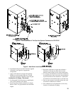
5. Start at vent connector on burner enclosure (rear
boiler jacket) and work towards the combustion air
terminal.
6. Size roof opening to allow easy insertion of
combustion air piping and allow proper installation
of ashing and storm collar to prevent moisture
from entering the structure.
a. Use appropriately designed vent ashing
when passing through roofs. Follow ashing
manufacturers’ instructions for installation
procedures.
b. Extend combustion air pipe to maintain
minimum vertical and horizontal distance of
twelve (12) inches from roof surface. Allow
additional vertical distance for expected snow
accumulation. Provide brace as required.
c. Install storm collar on combustion air pipe
immediately above ashing. Apply Dow
Corning Silastic 732 RTV Sealant between
combustion air pipe and storm collar to provide
weather-tight seal.
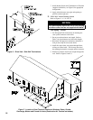
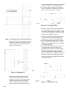
7. Install Rodent Screen and Combustion Air Terminal
(supplied with boiler), see Figure 8 for appropriate
conguration.
8. Brace exterior piping if required.
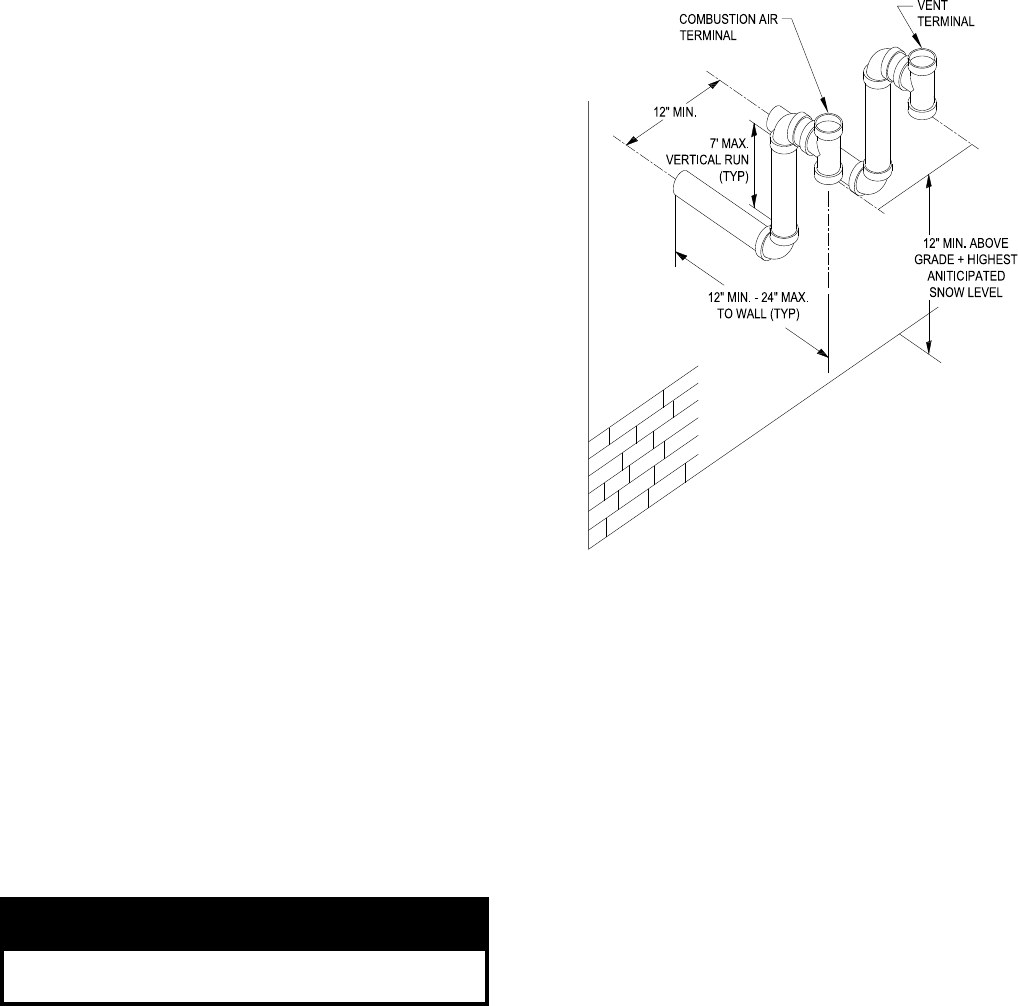
G. Optional Snorkel CPVC/PVC Horizontal Vent
System
Refer to Figures 3, 4, 5, 7, 8 and 11.
This installation will allow a maximum of seven (7) feet
vertical exterior run of the vent/combustion air piping
to be installed on the CPVC/PVC horizontal venting
application (Section E).
NOTICE
Exterior run to be included in equivalent vent/
combustion air lengths.
Vent Piping - Snorkel
1. See Paragraph D for instructions on attaching the
vent system connector to the boiler.
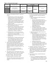
2. Do not exceed maximum vent length. Refer to
Table 7 for pipe diameters and allowable lengths.
3. Horizontal vent pipe must maintain a minimum ¼
inch per foot slope down towards boiler
4. After penetrating wall/thimble, install a Schedule
40 PVC 90° elbow so that the elbow leg is in the up
direction.
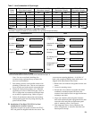
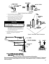
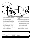
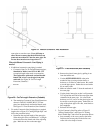
5. Install maximum vertical run of seven (7) feet of
Schedule 40 PVC vent pipe. See Figure 11.
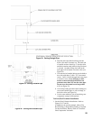
Figure 11: Direct Vent - Optional Side Wall
Snorkel Terminations
6. At top of vent pipe length install another PVC 90°
elbow so that elbow leg is opposite the building’s
exterior surface.
7. Install Rodent Screen and Vent Terminal (supplied
with boiler), see Figure 8 for appropriate
conguration.
8. Brace exterior piping if required.
Combustion Air Piping - Snorkel
1. See Paragraph D for instructions on attaching the
vent system connector to the boiler.
2. Do not exceed maximum combustion air length.
Refer to Table 7 for pipe diameters and allowable
lengths.
3. Horizontal combustion air pipe must maintain a
minimum ¼ inch per foot slope down towards
terminal, when possible. If not, slope toward boiler.
4. After penetrating wall, install a Schedule 40 PVC
90
o
elbow so that elbow leg is in the up direction.