


21
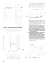
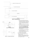
The direct vent termination location is restricted as
follows:
a. Minimum twelve (12) inches above grade plus
normally expected snow accumulation level, or
minimum seven (7) feet above grade, if direct
vent terminal is located adjacent to public
walkway. Do not install the terminal over public
walkway where local experience indicates that
appliance ue gas vapor or condensate creates a
nuisance or hazard.
b. Minimum three (3) feet above any forced air
inlet located within ten (10) feet.
c. Minimum four (4) feet horizontally from electric
meters, gas meters, regulators and relief valves.
This distance may be reduced if equipment is
protected from damage due to ue gas vapor or
condensation by enclosure, overhang, etc.
d. Minimum twelve (12) inches below, above or
horizontally from any air opening into a building
(window, door or gravity air inlet).
e. Minimum twelve (36) inches horizontally from a
building corner.
f. Minimum twelve (12) inches vertically from any
roof overhang twelve (12) inches or less wide.
If a roof overhang width exceeds twelve (12)
inches the terminal vertical clearance must be
increased to avoid ue vapor condensation.
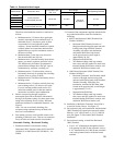
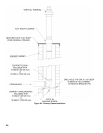
8. Enclose vent passing through occupied or
unoccupied spaces above the boiler with material
having a re resistance rating of at least equal to the
rating of the adjoining oor or ceiling. Maintain
minimum clearances to combustible materials. See
Figure 2.
Note: For one or two family dwellings, re
resistance rating requirement may not need to be
met, but is recommended.
9. Plan venting system to avoid possible contact with
plumbing or electrical wires. Start at vent connector
on top of boiler and work towards vent terminal.
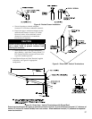
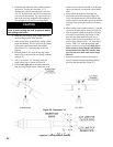
Concentric Venting - Horizontal Venting
1. Permitted terminals for horizontal venting:
Horizontal (Wall) Terminal, either 80/125 mm (P/N
101808-01) or 100/150 mm (P/N 101809-01) - see
Table 8.
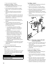
2. Concentric Vent components supplied with the boiler
are packed inside boiler carton and include the
following:
a. 80/125 mm Horizontal (Wall) Terminal, Part
Number 101808-01
• Horizontal (Wall) Terminal consists of
Straight section having plain male end with
locking band clamp installed; Terminal
Assembly with offset vent termination,
and Outside Wall Plate, both riveted
on the opposite end; overall length is
approximately 28-1/8”.
• Separate Inside Wall Plate
• Two Hardware Bags (each bag contains
four screws and four anchors) to attach vent
terminal Outside Wall Plate to exterior wall
and Inside Wall Plate to interior wall.
b. 100/150 mm Horizontal (Wall) Terminal, Part
Number 101809-01
• Horizontal Concentric Vent Terminal, which
consists of Straight section having plain
male end with locking band clamp installed;
Terminal Assembly with offset vent
termination, and Outside Wall Plate, both
riveted on the opposite end); overall length
is approximately 31-1/8”.
• Separate Inside Wall Plate.
• Two Hardware Bags (each bag contains
four screws and four anchors) to attach vent
terminal Outside Wall Plate to exterior wall
and Inside Wall Plate to interior wall.
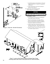
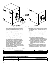
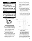
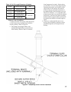
14. Installation of the Boiler Concentric Vent Collar is
covered in Section I above. See Figure 12.
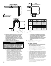
15. For horizontal (side wall) installation, the Horizontal
(Wall) Terminal will extend past outer wall surface
either by 4-1/4” (80/125 mm), or, 5-1/2” (100/150
mm). See Figure 13 “Horizontal (Wall) Terminal
Installation”.
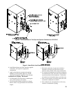
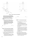
17. For horizontal venting, to install the Horizontal
(Wall) Terminal:
a. Cut a 5-1/2” diameter hole through the exterior
wall opening (for 80/125 mm concentric vent) or
6-1/2” diameter hole (for 100/150 mm concentric
vent) at the planned location of the horizontal
terminal.
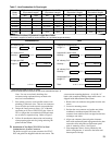
Table 11: Concentric Vent Length
Boiler Model Concentric Vent
Inner/Outer Pipe
Dia., mm
Vent Length
Wall Opening Diameter
Minimum * Maximum
ALP080
Factory Supplied
Horizontal (Wall) Terminal
80/125 mm 21-7/8 in
Total of 60
Equivalent ft.
5-1/2 in
ALP105
ALP150
ALP210
ALP285
Factory Supplied
Horizontal (Wall) Terminal
100/150 mm 32 in 6-1/2 in
ALP399
N
ote: * With optional concentric vent components. See Table 10 for details.