


32
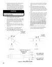
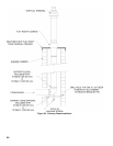
1. ALP080 thru ALP285 Boiler Models
a. Locate and remove ¾” NPT x close black nipple,
¾” NPT black tee, ¾” MPT x ¾” FPT Pressure
Relief Valve, ¾” NPT Drain Valve.
b. Install close nipple into tee branch, then, screw
the assembly into boiler left side front ¾”
tapping making sure tee run outlets are in vertical
plane and parallel to boiler side.
c. Mount ¾” MPT x ¾” FPT Pressure Relief Valve
into the tee top outlet.
d. Install Drain Valve into the tee bottom outlet.
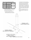
2. ALP399 Boiler Model
a. Locate and remove (2) ¾” NPT x close black
nipples, ¾” NPT black tee, ¾” FPT x ¾” FPT
Pressure Relief Valve, ¾” NPT Drain Valve.
b. Install close nipple into tee branch, then, screw
the assembly into boiler left side front ¾”
tapping making sure tee run outlets are in vertical
plane and parallel to boiler side.
c. Install the second close nipple into tee run top
outlet.
d. Mount ¾” FPT x ¾” FPT Pressure Relief Valve
into the tee top outlet.
e. Install Drain Valve into the tee bottom outlet.
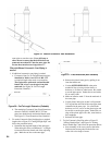
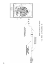
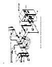
3. ALP080 thru ALP210 Boiler Models
a. Locate and remove 1” NPT x 4” long black
nipple, 1” x 1” x 1” NPT black tee, 1” x ¼”
NPT black reducing bushing and Temperature &
Pressure Gauge.
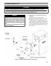
b. Mount the nipple into 1” boiler supply tapping
(see Figure 1A), then, install the tee onto the
nipple, making sure 1” branch outlet is in
horizontal plane and facing the boiler front.
c. Install 1” x ¼” NPT black reducing bushing
into the tee branch, then, put in Temperature &
Pressure Gauge.
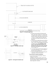
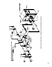
4. ALP285 Boiler Model
a. Locate and remove 1¼” NPT x 2” long black
nipple, 1¼” x 1¼” x ¾” NPT black tee, ¾” x ¼”
NPT black reducing bushing and Temperature &
Pressure Gauge.
b. Mount the nipple into 1¼” boiler supply tapping
(see Figure 1B), then, install the tee onto the
nipple, making sure ¾” branch outlet is in
horizontal plane and facing the boiler front.
c. Install ¾” x ¼” NPT black reducing bushing
into the tee branch, then, put in Temperature &
Pressure Gauge.
5. ALP399 Boiler Model
a. Locate and remove 1½” NPT x 2” long black
nipple, 1½” x 1½” x ¾” NPT black tee, ¾” x ¼”
NPT black reducing bushing and Temperature &
Pressure Gauge.
b. Mount the nipple into 1½” boiler supply tapping
(see Figure 1B), then, install the tee onto the
nipple, making sure ¾” branch outlet is in
horizontal plane and facing the boiler front.
c. Install ¾” x ¼” NPT black reducing bushing
into the tee branch, then, put in Temperature &
Pressure Gauge.