


11
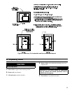
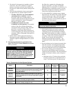
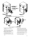
2. The Alpine™ is designed to be installed as a Direct
Vent boiler. The air for combustion is supplied
directly to the burner enclosure from outdoors and
ue gases are vented directly outdoors (through wall
or roof).
3. The following combustion air/vent system options
are approved for use with the Alpine™ boilers:
i. Two-Pipe CPVC/PVC Gas Vent/Combustion
Air System (factory standard) - separate
CPVC/PVC pipe serves to expel products of
combustion and separate PVC pipe delivers fresh
outdoor combustion air. Refer to Paragraph C
through F for specic details.
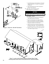
ii. Combination Concentric Gas Vent/
Combustion Air Inlet (optional) - the assembly
consists of inner re resistant polypropylene
vent pipe and outer steel pipe casing. The inner
pipe serves as conduit to expel products of
combustion, while outdoor fresh combustion air
is drawn through the space between the inner and
outer pipes. Refer to Paragraphs G through P for
specic details.
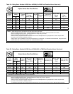
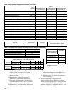
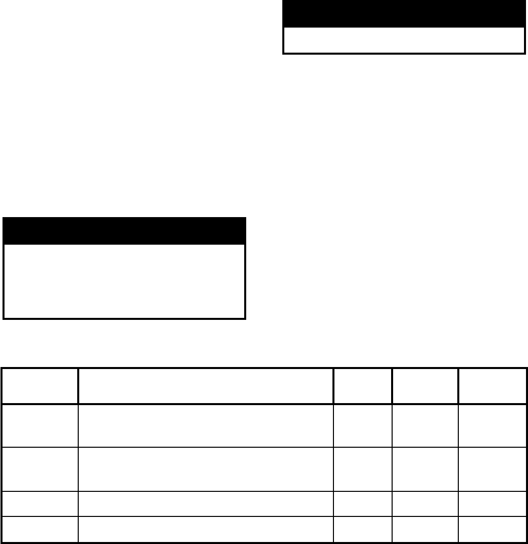
4. Refer to Table 3 and the appropriate drawings to
determine the proper conguration of either factory
standard or optional venting/combustion air system
details.
C. The following information is applicable for Two-
Pipe CPVC/PVC Gas Vent/Combustion Air System
(factory standard).
WARNING
All CPVC vent components (supplied with boiler)
must be used for near-boiler vent piping before
transitioning to Schedule 40 PVC pipe (ASTM
2665) components for remainder of vent system.
CPVC vent components must be used prior to
exit of any closet or conned space.
See
Table 6 for complete list of Burnham Vent
System Components. Use single wall thimble
[Burnham Part No. 102180-01 (3”), 102181-01 (4”)]
when penetrating a combustible wall for vent only.
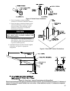
1.
Horizontal vent pipe must maintain a minimum ¼
inch per foot slope down towards boiler.
2. Use noncombustible ¾ inch pipe strap to support
horizontal runs and maintain vent location and slope
while preventing sags in pipe. Maximum support
spacing is four (4) feet. Avoid low spots where
condensate may pool. Do not penetrate any part of
the vent system with fasteners.
WARNING
All condensate that forms in the vent must be
able to drain back to the boiler.
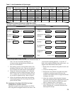
3.
Vent length restrictions are based on equivalent
length of vent/combustion air pipe (total length
of straight pipe plus equivalent length of ttings).
Maximum vent/combustion air lengths are listed in
Table 7. Do not exceed maximum vent/combustion
air lengths. Table 6 lists equivalent lengths for
ttings. Do not include vent/combustion air
terminals in equivalent feet calculations. See
“Combustion Air/Vent, Equivalent Length Work
Sheet”.
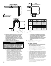
4. Provide minimum service clearance between boiler
back and concentric vent exiting through outside
wall, for concentric vent installation/replacement
and/or ue temperature sensor service/replacement.
5. Do not install venting system components on
the exterior of the building except as specically
required by these instructions. The vent termination
location is restricted as follows (refer to Figures 6
and 9):
a.
Minimum twelve (12) inches above grade plus
normally expected snow accumulation level, or
seven (7) feet above grade, if located adjacent
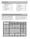
Option Description
Additional
Vent Kit
Required
Components
Included with
Boiler
Installation
Drawing and
Specication
TWO-PIPE
CPVC/PVC
HORIZONTAL
Direct Vent (sealed combustion) with both the vent pipe and
combustion air pipe terminating horizontally (through a sidewall)
with individual penetrations for the vent and combustion air
piping and terminals.
No See Table 4 See Figure 6
TWO-PIPE
CPVC/PVC
V
ERTICAL
Direct Vent (sealed combustion) with both the vent pipe and
combustion air pipe terminating vertically (through the roof) with
individual penetrations for the vent and combustion air piping
and terminals.
No See Table 4
See Figures
9 and 10
CONCENTRIC
HORIZONTAL
Direct Vent (sealed combustion) the concentric vent pipe
terminates horizontally (through a sidewall).
N
o See Table 9 See Figure 13
CONCENTRIC
VERTICAL
Direct Vent (sealed combustion) the concentric vent pipe
terminates vertically (through the roof).
Yes See Table 9 See Figure 19
Table 3: Combustion Air/Vent System Options