


WARNING: The unit cabinet must have an uninter-
rupted or unbroken ground to minimize personal injury if
an electrical fault should occur. The ground may consist
of electrical wire or metal conduit when installed in
accordance with existing electrical codes. Failure to
follow this warning can result in an electric shock, fire, or
death.
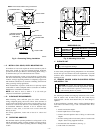
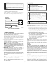
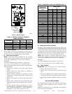
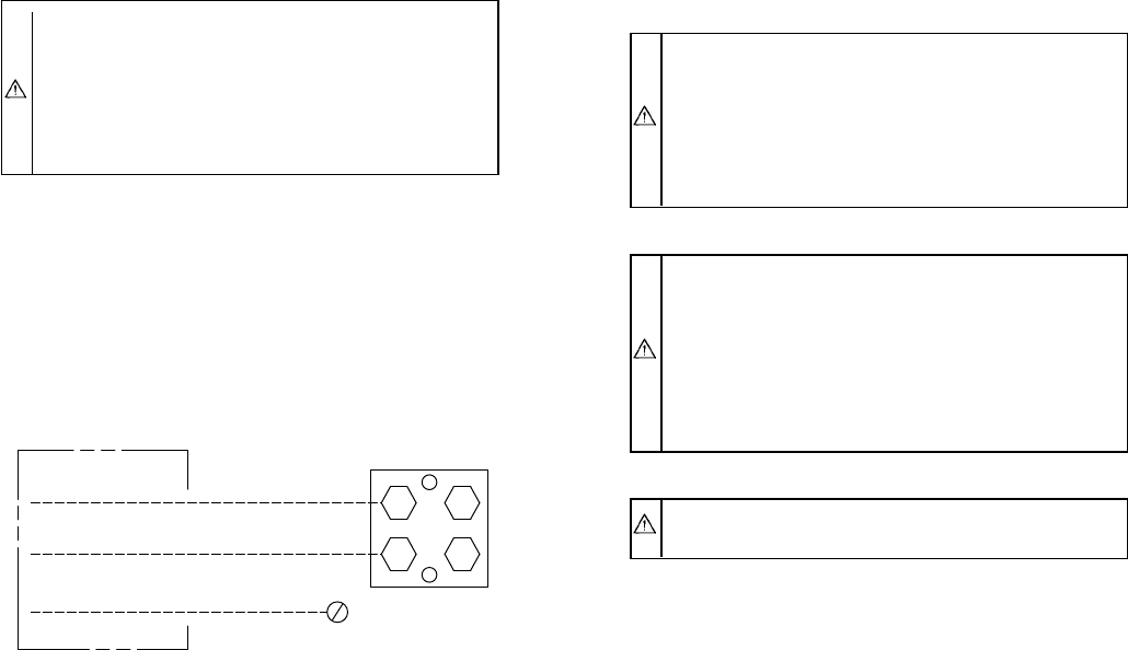
B. Connect Ground and Power Wires
Connect ground wire to ground connection in control box for
safety. Connect power wiring to contactor as shown in Fig. 8.
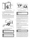
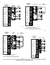
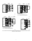
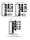
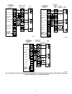
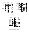
C. Connect Control Wiring
Route 24-v control wires through control wiring grommet and
connect leads to control wiring. (See Fig. 9–14.)
Use No. 18 AWG color-coded, insulated (35°C minimum) wire. If
thermostat is located more than 100 ft from unit, as measured
along the control voltage wires, use No. 16 AWG color-coded wire
to avoid excessive voltage drop.
All wiring must be NEC Class 1 and must be separated from
incoming power leads.
Use furnace transformer, fan coil transformer, or accessory trans-
former for control power, 24-v/40-va minimum.
NOTE: Use of available 24-v accessories may exceed the mini-
mum 40-va power requirement. Determine total transformer load-
ing and increase the transformer capacity or split the load with an
accessory transformer as required.
IMPORTANT: Check factory wiring and wire connections to
ensure terminations are secured properly. Check wire routing to
ensure wires are not in contact with tubing, sheet metal, etc.
XI. COMPRESSOR CRANKCASE HEATER
When equipped with a crankcase heater, furnish power to heater a
minimum of 24 hr before starting unit. To furnish power to heater
only, set thermostat to OFF and close electrical disconnect to
outdoor unit.
A crankcase heater is required if refrigerant tubing is longer than
50 ft.
XII. INSTALL ELECTRICAL ACCESSORIES
Refer to the individual instructions packaged with kits or acces-
sories when installing.
XIII. START-UP
CAUTION: To prevent compressor damage or personal
injury, observe the following:
• Do not overcharge system with refrigerant.
• Do not operate unit in a vacuum or at negative pressure.
• Do not disable low-pressure switch.
In scroll compressor applications:
• Dome temperatures may be hot.
CAUTION: To prevent personal injury wear safety
glasses, protective clothing, and gloves when handling
refrigerant and observe the following:
• Back seating service valves are not equipped with
Schrader valves. Fully back seat (counter clockwise)
valve stem before removing gage port cap.
• Front seating service valves are equipped with Schrader
valves.
CAUTION: Do not vent refrigerant to atmosphere. Re-
cover during system repair or final unit disposal.
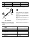
Follow these steps to properly pumpdown a system and avoid
negative suction pressure.
1. Fully back seat (open) liquid and vapor tube service valves.
2. Unit is shipped with valve stem(s) front seated (closed) and
caps installed. Replace stem caps after system is opened to
refrigerant flow. Replace caps finger-tight and tighten with
wrench an additional 1/12 turn.
3. Close electrical disconnects to energize system.
4. Set room thermostat to desired temperature. Be sure set
point is below indoor ambient temperature.
5. Set room thermostat to HEAT or COOL and fan control to
ON or AUTO mode, as desired. Operate unit for 15
minutes. Check system refrigerant charge.
A. Sequence of Operation
NOTE: Defrost control board may be equipped with 5-minute
lockout timer which may be initiated upon any interruption of
power.
With power supplied to indoor and outdoor units, transformer is
energized.
COOLING
On a call for cooling, thermostat makes circuits R-O, R-Y, and
R-G. Circuit R-O energizes reversing valve, switching it to cooling
position. Circuit R-Y energizes contactor, starting outdoor fan
motor and compressor circuit. R-G energizes indoor unit blower
relay, starting indoor blower motor on high speed.
When thermostat is satisfied, its contacts open, de-energizing the
contactor and blower relay. Compressor and motors should stop.
NOTE: If indoor unit is equipped with a time-delay relay circuit,
the blower runs an additional 90 sec to increase system efficiency.
HEATING
On a call for heating, thermostat makes circuits R-Y and R-G.
Circuit R-Y energizes contactor, starting outdoor fan motor and
compressor. Circuit R-G energizes indoor blower relay, starting
blower motor on high speed.
Should temperature continue to fall, R-W2 is made through
second-stage room thermostat bulb. Circuit R-W2 energizes a
sequencer, bringing on first bank of supplemental electric heat and
Fig. 8—Line Power Connections
A91056
DISCONNECT
PER N. E. C. AND/OR
LOCAL CODES
CONTACTOR
GROUND
LUG
FIELD GROUND
WIRING
FIELD POWER
WIRING
—5—
→
→
→