


II. INSTALL ON A SOLID, LEVEL MOUNTING PAD
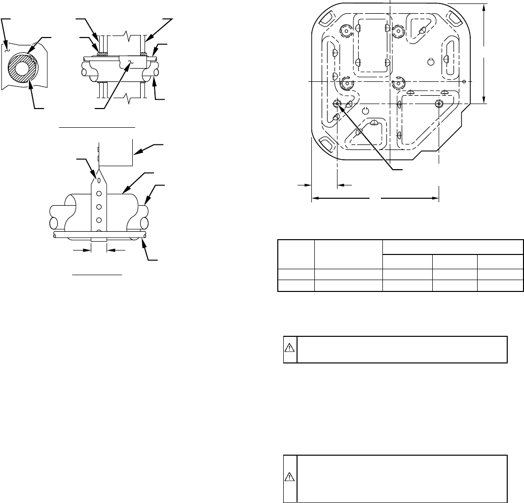
If conditions or local codes require the unit be attached to pad, tie
down bolts should be used and fastened through knockouts
provided in unit base pan. Refer to unit mounting pattern in Fig. 3
to determine base pan size and knockout hole location.
On rooftop applications, mount on level platform or frame. Place
unit above a load-bearing wall and isolate unit and tubing set from
structure. Arrange supporting members to adequately support unit
and minimize transmission of vibration to building. Consult local
codes governing rooftop applications.
Roof mounted units exposed to winds above 5 mph may require
wind baffles to achieve adequate defrost. Consult Low-Ambient
Guideline for wind baffle construction.
NOTE: Unit must be level to within ± 2˚ (± 3/8 in./ft) per
compressor manufacturer specifications.
III. CLEARANCE REQUIREMENTS
When installing, allow sufficient space for airflow clearance,
wiring, refrigerant piping, and service. Allow 30-in. clearance to
service end of unit and 48 in. above unit. For proper airflow, a 6-in.
clearance on 1 side of unit and 12 in. on all remaining sides must
be maintained. Maintain a distance of 24 in. between units.
Position so water, snow, or ice from roof or eaves cannot fall
directly on unit.
On rooftop applications, locate unit at least 6 in. above roof
surface.
IV. OPERATING AMBIENTS
The minimum outdoor operating ambient in cooling mode is 55˚F,
and the maximum outdoor operating ambient in cooling mode is
125˚F. The maximum outdoor operating ambient in heating mode
is 66˚F.
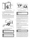
V. ELEVATE UNIT
CAUTION: Accumulation of water and ice in base pan
may cause equipment damage.
In areas where prolonged freezing temperatures are encountered,
elevate unit per local climate and code requirements to provide
clearance above estimated snowfall level and ensure adequate
drainage of unit.
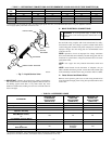
VI. REMOVE INDOOR CHECK-FLO-RATER® PISTON
AND INSTALL TXV
CAUTION: For proper unit operation and reliability,
units must be installed with field-supplied hard shutoff
TXV. Do not install with evaporator coils having capil-
lary tube metering devices or pistons.
For TXV kit part number and charging instructions, refer to TXV
label in outdoor unit. If indoor unit (fan coil) comes factory
equipped with a bi-flow hard shutoff TXV, no TXV change is
required.
If TXV installation is required, remove existing Check-Flo-Rater
from indoor coil. Refer to Fig. 4 and 5 and install TXV kit as
follows:
1. Install suction tube adapter.
2. Install liquid flare-to-sweat adapter.
3. Connect external equalizer tube to fitting on suction tube
adapter.
4. Position sensing bulb on horizontal portion of suction tube
adapter. Secure using supplied hardware.
5. Insulate bulb after installation. (See Fig. 5.)
6. Leak check all connections.
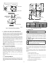
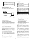
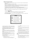
Fig. 2—Connecting Tubing Installation
A94028
INSULATION
VAPOR TUBE
LIQUID TUBE
OUTDOOR WALL INDOOR WALL
LIQUID TUBE
VAPOR TUBE
INSULATION
CAULK
Avoid contact between tubing and structureNOTE:
THROUGH THE WALL
HANGER STRAP
(AROUND VAPOR
TUBE ONLY)
JOIST
1″ MIN.
SUSPENSION
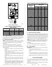
Fig. 3—Mounting Unit to Pad
DIMENSIONS (IN.)
UNIT
SIZE
MINIMUM
MOUNTING PAD
DIMENSIONS
TIEDOWN KNOCKOUT LOCATIONS
ABC
018 22-1/2 X 22-1/2 3-11/16 18-1/8 14-3/8
024–060 30 X 30 6-1/2 23-1/2 20
A94199
C
B
A
3
⁄
8
″D. (9.53) TIEDOWN
KNOCKOUTS (2) PLACES
—2—
→
→