


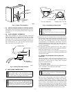
IMPORTANT: Check to be certain factory tubing on both indoor
and outdoor unit has not shifted during shipment. Ensure tubes are
not rubbing against each other or any sheet metal. Pay close
attention to feeder tubes, making sure wire ties on feeder tubes are
secure and tight.
X. MAKE ELECTRICAL CONNECTIONS
WARNING: To avoid personal injury or death, do not
supply power to unit with compressor terminal box cover
removed.
Be sure field wiring complies with local and national fire, safety,
and electrical codes, and voltage to system is within limits shown
on unit rating plate. Contact local power company for correction of
improper voltage. See unit rating plate for recommended circuit
protection device.
NOTE: Operation of unit on improper line voltage constitutes
abuse and could affect unit reliability. See unit rating plate. Do not
install unit in system where voltage may fluctuate above or below
permissible limits.
NOTE: Use copper wire only between disconnect switch and
unit.
NOTE: Install branch circuit disconnect of adequate size per
NEC to handle unit starting current. Locate disconnect within sight
from and readily accessible from unit, per Section 440-14 of NEC.
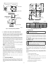
A. Route Ground and Power Wires
Remove access panel to gain access to unit wiring. Extend wires
from disconnect through power wiring hole provided and into unit
control box.
→ TABLE 1—REFRIGERANT CONNECTIONS AND RECOMMENDED LIQUID AND VAPOR TUBE DIAMETERS (IN.)
UNIT
SIZE
LIQUID VAPOR VAPOR (LONG LINE)
Connection Diameter Tube Diameter Connection Diameter Tube Diameter Connection Diameter Tube Diameter
018 3/8 3/8 5/8 5/8 5/8 3/4
024 3/8 3/8 3/4 3/4 3/4 3/4
030, 036 3/8 3/8 3/4 3/4 3/4 7/8
042 3/8 3/8 7/8 7/8 7/8 1-1/8
048, 060 3/8 3/8 7/8 1-1/8 7/8 1-1/8
NOTES:
1. Tube diameters are for lengths up to 50 ft. For tubing lengths greater than 50 ft, consult Residential Split System Long-Line Application Guideline.
2. Do not apply capillary tube indoor coils to these units.
→ TABLE 2—ACCESSORY USAGE
ACCESSORY
REQUIRED FOR
LOW-AMBIENT
APPLICATIONS
(BELOW 55°F)
REQUIRED FOR
LONG-LINE
APPLICATIONS*
(OVER 50 FT)
REQUIRED FOR
BURIED LINE
APPLICATIONS†
(OVER 3 FT)
Crankcase Heater Yes Yes Yes
Evaporator Freeze Thermostat Yes No No
Accumulator No No Yes
Compressor Start Assist
Capacitor and Relay
Yes Yes Yes
Low-Ambient Controller,
MotorMaster® Control,
or
Low-Ambient Pressure Switch
Yes No No
Wind Baffle See Low-Ambient Instructions No No
Unit Risers Recommended No No
Liquid-Line Solenoid Valve
or
Hard Shutoff TXV
No
See Long-Line
Application
Guideline
Yes
Ball Bearing Fan Motor Yes‡ No No
* For tubing line sets between 50 and 175 ft, refer to Residential Split System Long-Line Application Guideline.
† For buried line applications, refer to Residential Split System Buried-Line Application Guideline.
‡ Required for Low-Ambient Controller (full modulation feature) and MotorMaster Control only.
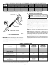
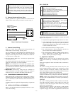
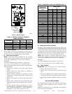
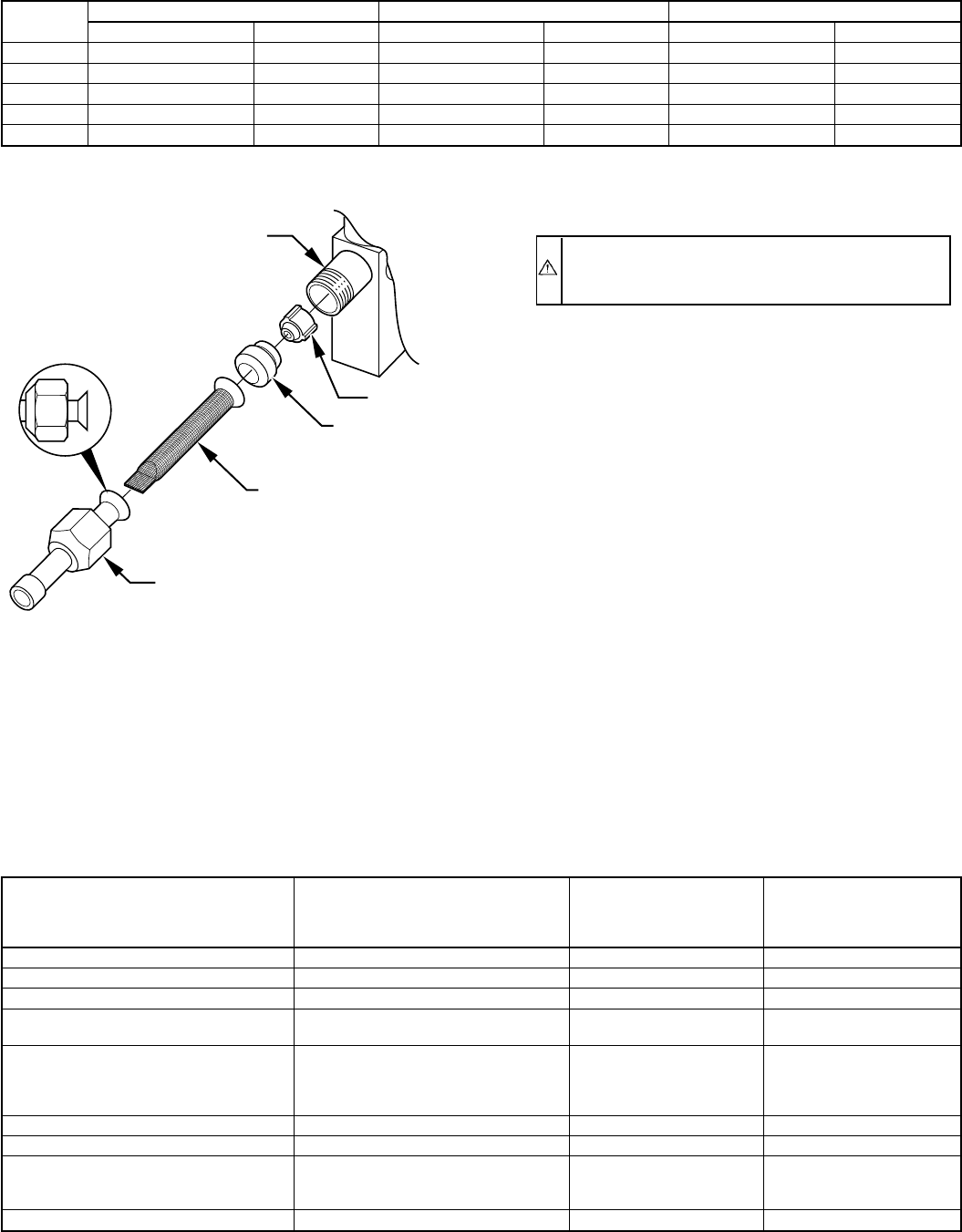
→ Fig. 7—Liquid Service Valve
A97512
PISTON BODY
PISTON
PISTON
RETAINER
SWEAT/FLARE ADAPTER
STRAINER
—4—
→