


providing electrical potential to second heater sequencer (if used).
If outdoor temperature falls below setting of outdoor thermostat
(field-installed option), contacts close to complete circuit and bring
on second bank of supplemental electric heat.
When thermostat is satisfied, its contacts open, de-energizing
contactor and sequencer. All heaters and motors should stop.
DEFROST
The defrost control is a time/temperature control which includes a
field-selectable (quick-connects located at board edge) time period
between defrost cycles (30, 50, or 90 minutes), factory set at 90
minutes.
The electronic timer and defrost cycle start only when contactor is
energized and defrost thermostat is closed.
Defrost mode is identical to cooling mode except that outdoor fan
motor stops and second-stage heat is turned on to continue
warming conditioned space.
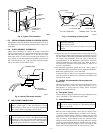
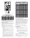
To initiate defrost, the defrost thermostat must be closed. This can
be accomplished as follows:
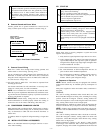
1. Turn off power to outdoor unit.
2. Disconnect outdoor fan motor lead from OF2 on control
board. (See Fig. 15.) Tape lead to prevent grounding.
3. Restart unit in heating mode, allowing frost to accumulate
on outdoor coil.
4. After a few minutes in heating mode, liquid line tempera-
ture should drop below closing point of defrost thermostat
(approximately 30˚F).
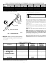
5. Short between speed-up terminals with a flat-bladed screw-
driver. (See Fig. 15.) This reduces the timing sequence to
1/256th of original time. (See Table 3.)
6. When you hear reversing valve change position, remove
screwdriver immediately; otherwise, control will terminate
normal 10-minute defrost cycle in approximately 2 sec.
NOTE: Length of defrost cycle is dependent on the length of time
it takes to remove screwdriver from test pins after reversing valve
has shifted.
7. Unit will remain in defrost for remainder of defrost cycle
time or until defrost thermostat reopens at approximately
80˚F coil temperature of liquid line.
8. Turn off power to outdoor unit and reconnect fan motor lead
to OF2 on control board. (See Fig. 15.)
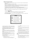
A97413
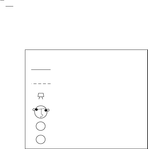
LEGEND
24 VOLT FACTORY WIRING
24 VOLT FIELD WIRING
FIELD SPLICE CONNECTION
OUTDOOR THERMOSTAT
EMERGENCY HEAT RELAY
SUPPLEMENTAL HEAT RELAY
SHR
EHR
ODT
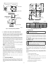
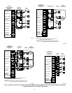
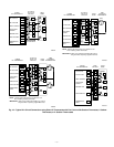
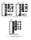
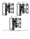
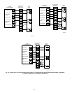
WIRING DIAGRAM NOTES:
1. BRYANT THERMOSTAT WIRING DIAGRAMS ARE ONLY ACCURATE FOR MODEL NUMBERS BEGINNING
WITH TSTAT_______.
2. WIRING MUST CONFORM TO NEC OR LOCAL CODES.
3. SOME UNITS ARE EQUIPPED WITH PRESSURE SWITCH(ES), TEMPERATURE SWITCH, OR 5-MINUTE COM-
PRESSOR CYCLE PROTECTION. CONNECT 24-V FIELD WIRING TO FACTORY-PROVIDED STRIPPED LEADS.
4. A LIQUID-LINE SOLENOID VALVE IS REQUIRED ON SOME UNITS.
5. THERMOSTATS ARE FACTORY CONFIGURED WITH 5-MINUTE COMPRESSOR CYCLE PROTECTION AND 4
CYCLES PER HR LIMIT. SEE THERMOSTAT INSTALLATION INSTRUCTIONS FOR DETAILS.
6. TO STAGE ELECTRIC RESISTANCE HEAT, CONSULT OUTDOOR THERMOSTAT INSTALLATION INSTRUC-
TIONS.
7. FOR DUAL FUEL THERMOSTATS, UNDERLINED LETTER ON DUAL TERMINAL INDICATES ITS USAGE.
FOR EXAMPLE: O/W2 MEANS O
O/W2 MEANS W2
OUTDOOR TEMPERATURE SENSOR MUST BE ATTACHED IN ALL DUAL FUEL INSTALLATIONS.
JUMPER WIRE BETWEEN O/W2 AND L THERMOSTAT TERMINALS MUST BE PRESENT.
8. Y1 AND O CONNECTIONS TO 2-STAGE FURNACES MAY NOT EXIST OR MAY ONLY BE A WIRE RATHER
THAN A SCREW TERMINAL.
—11—