


XIV. CHECK CHARGE
Factory charge is shown on unit rating plate. To check charge in
cooling mode, refer to Cooling Only Procedure. To check charge
in heating mode, refer to Heating Check Chart Procedure.
A. Cooling Only Procedure
NOTE: If subcooling charging conditions are not favorable,
charge must be weighed in accordance with unit rating plate ± 0.6
oz/ft of 3/8-in. liquid line above or below 15 ft respectively.
EXAMPLE:
To calculate additional charge required for a 25-ft line set:
25 ft - 15 ft = 10 ft X 0.6 oz/ft=6ozofadditional charge
Units installed with cooling mode TXV require charging with the
subcooling method.
1. Operate unit a minimum of 10 minutes before checking
charge.
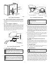
2. Measure liquid service valve pressure by attaching an
accurate gage to service port.
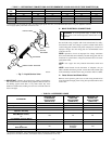
3. Measure liquid line temperature by attaching an accurate
thermistor type or electronic thermometer to liquid line near
outdoor coil.
4. Refer to unit rating plate for required subcooling tempera-
ture.
5. Refer to Table 4. Find the point where required subcooling
temperature intersects measured liquid service valve pres-
sure.
6. To obtain required subcooling temperature at a specific
liquid line pressure, add refrigerant if liquid line tempera-
ture is higher than indicated or reclaim refrigerant if
temperature is lower. Allow a tolerance of ± 3°F.
B. Heating Check Chart Procedure
To check system operation during heating cycle, refer to the
Heating Check Chart on outdoor unit. This chart indicates whether
a correct relationship exists between system operating pressure and
air temperature entering indoor and outdoor units. If pressure and
temperature do not match on chart, system refrigerant charge may
not be correct. Do not use chart to adjust refrigerant charge.
NOTE: When charging is necessary during heating season,
charge must be weighed in accordance with unit rating plate ± 0.6
oz/ft of 3/8-in. liquid line above or below 15 ft respectively.
EXAMPLE:
To calculate additional charge required for a 25-ft line set:
25 ft - 15 ft = 10 ft X 0.6 oz/ft=6ozofadditional charge
XV. FINAL CHECKS
IMPORTANT: Before leaving job, be sure to do the following:
1. Securely fasten all panels and covers.
2. Tighten service valve stem caps to 1/12-turn past finger
tight.
3. Leave User’s Manual with owner. Explain system operation
and periodic maintenance requirements outlined in manual.
4. Fill out Dealer Installation Checklist and place in customer
file.
CARE AND MAINTENANCE
For continuing high performance and to minimize possible equip-
ment failure, periodic maintenance must be performed on this
equipment.
Frequency of maintenance may vary depending upon geographic
areas, such as coastal applications.
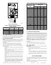
TABLE 3—DEFROST CONTROL SPEED-UP
TIMING SEQUENCE
PARAMETER
MINIMUM
(MINUTES)
MAXIMUM
(MINUTES)
SPEED-UP
(NOMINAL)
30-minute cycle 27 33 7 sec
50-minute cycle 45 55 12 sec
90-minute cycle 81 99 21 sec
10-minute cycle 9 11 2 sec
5 minutes 4.5 5.5 1 sec
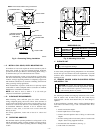
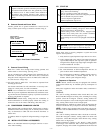
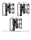
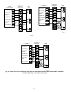
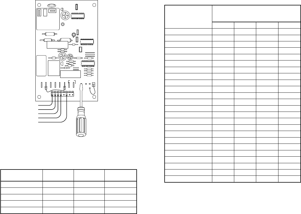
Fig. 15—Defrost Control
A91444
OF1
OF2
O
R
T2 Y
TI
DFT
C
TEST
30
50 90
W1
O
R
W2
Y
C
CES0110063,
CES0130024
TABLE 4—REQUIRED LIQUID-LINE TEMPERATURE (°F)
LIQUID
PRESSURE AT
SERVICE VALVE
(PSIG)
REQUIRED SUBCOOLING
TEMPERATURE
(°F)
5 101520
134 71 66 61 56
141 74 69 64 59
148 77 72 67 62
156 80 75 70 65
163 83 78 73 68
171 86 81 76 71
179 89 84 79 74
187 92 87 82 77
196 95 90 85 80
205 98 93 88 83
214 101 96 91 86
223 104 99 94 89
233 107 102 97 92
243 110 105 100 95
253 113 108 103 98
264 116 111 106 101
274 119 114 109 104
285 122 117 112 107
297 125 120 115 110
309 128 123 118 113
321 131 126 121 116
331 134 129 124 119
346 137 132 127 122
359 140 135 130 125
© 1997 Bryant Heating & Cooling Systems 7310 W. Morris St. Indianapolis, IN 46231
—12—
Printed in U.S.A. 663c181 Catalog No. 5366-300
→
→