


VII. CHECK OUTDOOR CHECK-FLO-RATER® PISTON
Check outdoor unit piston. Remove retainer on liquid service valve
and check piston size with matching number listed on outdoor unit
rating plate.
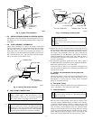
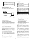
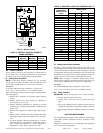
VIII. CHECK DEFROST THERMOSTAT
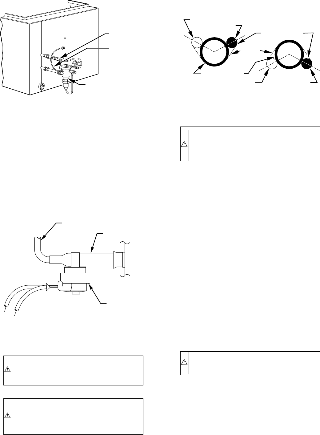
Check defrost thermostat to ensure it is properly located and
securely attached. There is a liquid header with a brass distributor
and feeder tube going into outdoor coil. At the end of 1 of the
feeder tubes, there is a 3/8-in. O.D. stub tube approximately 2 in.
long. (See Fig. 6.) The defrost thermostat should be located on stub
tube. Note that there is only 1 stub tube used with liquid header,
and on most units it is the bottom circuit.
IX. MAKE PIPING CONNECTIONS
WARNING: Relieve pressure and recover all refrigerant
before system repair or final unit disposal to avoid
personal injury or death. Use all service ports and open all
flow-control devices, including solenoid valves.
CAUTION: If ANY refrigerant tubing is buried, provide
a 6 in. vertical rise at service valve. Refrigerant tubing
lengths up to 36 in. may be buried without further special
consideration. For lengths above 36 in., refer to Residen-
tial Split System Buried-Line Application Guideline.
CAUTION: To prevent damage to unit or service valves
observe the following:
• Use a brazing shield.
• Wrap service valves with wet cloth or use a heat sink
material.
Outdoor units may be connected to indoor section using accessory
tubing package or field-supplied refrigerant grade tubing of correct
size and condition. For tubing requirements beyond 50 ft, substan-
tial capacity and performance losses can occur. Following the
recommendations in the Residential Split System Long-Line
Application Guideline will reduce these losses. Refer to Table 1
for field tubing equivalent line length. Refer to Table 2 for
accessory requirements.
For buried-line applications greater than 36 in., refer to Table 2
and Residential Split System Buried-Line Application Guideline.
Buried-line applications may not exceed 100 ft.
If refrigerant tubes or indoor coil are exposed to atmosphere, they
must be evacuated to 500 microns to eliminate contamination and
moisture in the system.
A. Outdoor Unit Connected to Factory-Approved
Indoor Unit
Outdoor unit contains correct system refrigerant charge for opera-
tion with indoor unit of same size when connected by 15 ft of
field-supplied or factory-accessory tubing. Check refrigerant
charge for maximum efficiency.
B. Refrigerant Tubing
Connect tubing to fittings on outdoor unit vapor and liquid service
valves. (See Table 1.) Use refrigerant grade tubing.
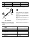
C. Sweat Connection
CAUTION: To avoid valve damage while brazing, ser-
vice valves must be wrapped in a heat-sinking material
such as a wet cloth.
Remove plastic retainer holding outdoor piston in liquid service
valve and connect sweat/flare adapter provided to valve. (See Fig.
7.) Connect refrigerant tubing to fittings on outdoor unit vapor and
liquid service valves. Service valves are closed from factory and
ready for brazing. After wrapping service valve with a wet cloth,
tubing set can be brazed to service valve using either silver bearing
or non-silver bearing brazing material. Consult local code require-
ments. Refrigerant tubing and indoor coil are now ready for leak
testing. This check should include all field and factory joints.
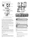
Fig. 4—Typical TXV Installation
A88382
THERMOSTATIC
EXPANSION
VALVE
EQUALIZER
TUBE
SENSING
BULB
COIL
Fig. 5—Positioning of Sensing Bulb
A81032
2 O'CLOCK
10 O'CLOCK
SENSING BULB
STRAP
SUCTION TUBE
8 O'CLOCK
4 O'CLOCK
7
⁄
8
IN. OD & SMALLER
LARGER THAN
7
⁄
8
IN. OD
Fig. 6—Defrost Thermostat Location
A97517
FEEDER TUBE
DEFROST
THERMOSTAT
STUB TUBE
—3—
→
→
→
→
→