


82
GUIDE SPECIFICATIONS — 524A
COMMERCIAL PACKAGED AIR-HANDLING UNIT
HVAC GUIDE SPECIFICATIONS
SIZE RANGE: 1,800 to 12,500 CFM, NOMINAL AIRFLOW 6 TO
25 TONS, NOMINAL COOLING
BRYANT MODEL NUMBERS: 524A-B (DIRECT-EXPANSION
COIL), 524A-C (HIGH-CAPACITY 4-ROW DIRECT-EXPANSION
COIL)
PART 1 — GENERAL
1.01 SYSTEM DESCRIPTION
A. Indoor, packaged air-handling unit for use in commercial
split systems. Unit shall have a multiposition design and
shall be capable of horizontal or vertical installation on a
floor or in a ceiling, with or without ductwork. (Only verti-
cal units are to be applied without ductwork.)
B. Unit with direct-expansion coil shall be used in a refriger-
ant circuit with a matching air-cooled condensing unit.
1.02 QUALITY ASSURANCE
A. Coils shall be designed and tested in accordance with
ASHRAE 15 Safety Code for Mechanical Refrigeration,
latest edition.
B. Unit shall be constructed in accordance with ETL and
ETL, Canada, standards and shall carry the ETL and
ETL, Canada, labels.
C. Unit insulation and adhesive shall comply with NFPA-90A
requirements for flame spread and smoke generation.
Insulation shall contain an EPA-registered immobilized
antimicrobial agent to effectively resist the growth of
bacteria and fungi as proven by tests in accordance with
ASTM standards G21 and 22.
D. Unit shall be manufactured in a facility registered to the
ISO 9001:2000 manufacturing quality standard.
E. Direct-expansion coils shall be burst and leak tested at
435 psi.
1.03 DELIVERY AND STORAGE
Units shall be stored and handled per manufacturer’s
recommendations.
PART 2 — PRODUCTS
2.01 EQUIPMENT
Indoor mounted, draw-thru, packaged air-handling unit
that can be used in a suspended horizontal configuration
or a vertical configuration. Unit shall consist of forward-
curved belt-driven centrifugal fan(s), motor and drive
assembly, prewired fan motor contactor, factory-installed
refrigerant metering devices (direct-expansion coil units),
cooling coil, 2-in. disposable air filters, and condensate
drain pans for vertical or horizontal configurations.
A. Base Unit:
1. Cabinet shall be constructed of mill-galvanized steel.
2. Cabinet panels shall be fully insulated with
1
/
2
-in.
fire-retardant material. Insulation shall contain an
EPA-registered immobilized antimicrobial agent to
effectively resist the growth of bacteria and fungi as
proven by tests in accordance with ASTM standards
G21 and 22.
3. Unit shall contain non-corroding condensate drain
pans for both vertical and horizontal applications.
Drain pans shall have connections on right and left
sides of unit to facilitate field connection. Drain pans
shall have the ability to be sloped toward the right or
left side of the unit to prevent standing water from
accumulating in pans.
4. Unit shall have factory-supplied 2-in. throwaway-type
filters installed upstream from the cooling coil. Filter
access shall be from either the right or left side of the
unit.
B. Coils:
Coils shall consist of 3 rows (524A-B) or 4 rows (524A-C)
of copper tubes with sine-wave aluminum fins bonded to
the tubes by mechanical expansion. Suction and liquid
line connections or supply and discharge connections
shall be made on the same side of the coil.
1. Direct-expansion coils shall feature factory-installed
thermostatic expansion valves (TXVs) for refrigerant
control. The TXVs shall be capable of external
adjustment. Coil tubing shall be internally rifled to
maximize heat transfer.
2. High-Capacity Coil:
The high-capacity 4-row coil consists of 4 rows of
3
/
8
-in. copper tubes with sine-wave aluminum fins
bonded to the tubes by mechanical expansion. Coil
tubing shall be internally rifled to maximize heat
transfer. Suction and liquid line connections shall be
made on the same side of the coil. Direct-expansion
coils shall feature factory-installed thermostatic
expansion valves (TXVs) for refrigerant control. The
TXVs shall be capable of external adjustment.
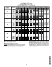
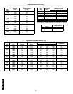
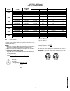
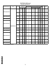
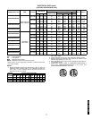
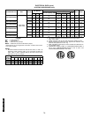
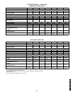
C. Operating Characteristics:
Unit shall be capable of providing
cfm airflow at an
external static pressure of in. wg.
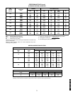
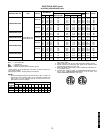
D. Motor:
Fan motor of the size and electrical characteristics speci-
fied on the equipment schedule shall be factory supplied
and installed.
Motors rated at 1.3 through 3.7 hp shall have internal
thermal overload protection. Motors rated at 5, 7
1
/
2
,and
10 hp shall be protected by a circuit breaker.
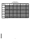
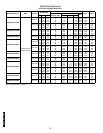
E. Special Features:
1. Alternate Motor and Drive:
An alternate motor and/or medium-static or high-
static drive shall be available to meet the airflow and
external static pressure requirements specified on
the equipment schedule.
2. External Paint:
Where conditions require, units shall be painted with
an American Sterling Gray finish.
3. Hot Water Coil:
Coil shall be 2-row, U-bend coil with copper tubes
and aluminum plate fins bonded to the tubes by
mechanical expansion. Coil shall be mounted in a
galvanized steel housing that shall be fastened to the
unit’s fan deck for blow-thru heating operation. Coil
shall have maximum working pressure of 150 psig.
4. Steam Distributing Coil:
Coil shall consist of one row of copper tubes with
aluminum plate fins, and shall have inner steam dis-
tributing tubes. Coil shall be mounted in a galvanized
steel housing and shall be fastened to the unit’s fan
deck for blow-thru heating operation. Coil shall have
maximum working pressure of 20 psig at 260 F.
50TFQ004-012
524A072-300