


54
APPLICATION DATA — 566D150-240, 566E150-240
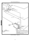
1. INSTALLATION — Select equipment to match or to be
slightly less than peak load. This provides better humidity
control, less unit cycling, and less part-load operation.
When selecting vapor line sizes, oil return must be evalu-
ated, particularly at part-load conditions.
The indoor fan must always be operating when outdoor unit
is operating.
Ductwork should be sized according to unit size, not build-
ing load.
To minimize the possibility of air recirculation, avoid the use
of concentric supply/return grilles.
Indoor equipment should be selected at no less than
300 cfm/ton.
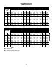
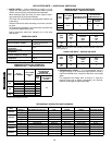
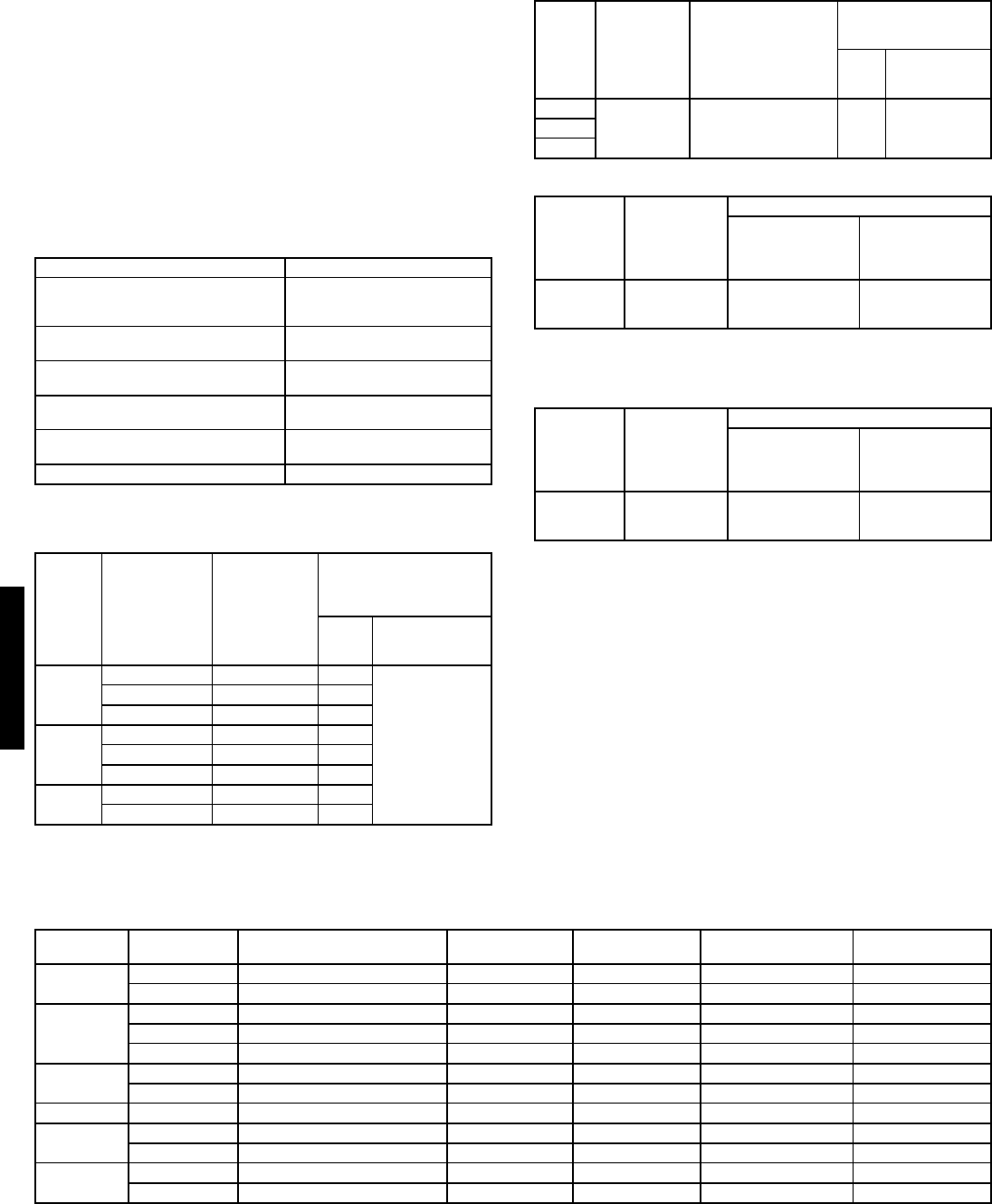
OPERATING LIMITS
MINIMUM OUTDOOR-AIR OPERATING
TEMPERATURE — 566D150-240 UNITS
*Requires field-installed unloader.
MINIMUM OUTDOOR-AIR OPERATING
TEMPERATURE — 566E150-240 UNITS
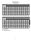
LIQUID LINE DATA — 566D150-240 UNITS
NOTE: Data above is for units operating at 45 F saturated suction and
95 F entering air.
LIQUID LINE DATA — 566E150-240 UNITS
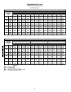
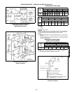
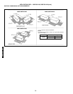
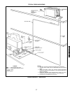
2. REFRIGERANT PIPING — It is recommended that the
refrigerant piping for all commercial split systems include a
liquid line solenoid valve, a liquid line filter drier, and a sight
glass.
For refrigerant lines longer than 75 lineal ft, a liquid line
solenoid valve and a suction accumulator are required.
Refer to the Refrigerant Specialties table.
REFRIGERANT SPECIALTIES PART NUMBERS
*Bushings required.
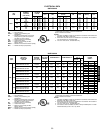
Maximum Outdoor 115 F
Minimum Outdoor Ambient
See Minimum Outdoor-Air
Operating Temperature
table below.
Minimum Return-Air
Temperature
55 F
Maximum Return-Air
Temperature
95 F
Normal Acceptable Saturation
Suction Temperature Range
25 to 55 F
Maximum Discharge
Temperature
295 F
Minimum Discharge Superheat 60 F
UNIT
566D
NO. OF
CYLINDERS
FULL LOAD
CAPACITY
(%)
MINIMUM
OUTDOOR-AIR
OPERATING
TEMPERATURE (F)
Base
Unit
With
Low-Ambient
Control
150
6 100 20
–20
46731
2* 33* 40
180
6 100 20
46733
2* 33* 47
240
4 100 15
25020
UNIT
566E
FULL LOAD
CAPACITY
(%)
SATURATED COND
TEMPERATURE (F)
MINIMUM
OUTDOOR-AIR
TEMPERATURE (F)
Base
Unit
With
Low-Ambient
Control
150
100/50 90 50 –20180
240
UNIT
566D
MAX
ALLOW.
LIFT
(ft)
LIQUID LINE
Max Allow.
Pressure
Drop
(psi)
Max Allow.
Temp
Loss
(°F)
150 67
72
180 82
240 87
UNIT
566E
MAX
ALLOW.
LIFT
(ft)
LIQUID LINE
Max Allow.
Pressure
Drop
(psi)
Max Allow.
Temp
Loss
(°F)
150
60 7 2
180
240
UNIT
LIQUID LINE
SIZE(in.)
LIQUID LINE
SOLENOID VALVE (LLSV)
LLSV
COIL
SIGHT
GLASS
FILTER
DRIER
SUCTION LINE
ACCUMULATOR
566D150
1
/
2
200RB7T4M AMG/24V AMI-1TT4 P502-8757S* S-7063
5
/
8
200RA8T5M AMG/24V AMI-1TT5 P502-8757S* S-7063
566D180
1
/
2
200RB7T4M AMG/24V AMI-1TT4 P502-8757S* S-7721
5
/
8
200RA8T5M AMG/24V AMI-1TT5 P502-8757S* S-7721
7
/
8
200RA8T7M AMG/24V AMI-1TT7 P502-8757S S-7721
566D240
5
/
8
200RA9T5M AMG/24V AMI-1TT5 P502-8757S* S-7721
7
/
8
200RA9T7M AMG/24V AMI-1TT7 P502-8757S S-7721
566E150
1
/
2
200RB5T4M Qty 2 AMG/24V Qty 2 AMI-1TT4 Qty 2 P502-8304S Qty 2 S-7063S* Qty 2
566E180
1
/
2
200RB5T4M Qty 2 AMG/24V Qty 2 AMI-1TT4 Qty 2 P502-8304S Qty 2 S-7063S Qty 2
5
/
8
200RB5T5M Qty 2 AMG/24V Qty 2 AMI-1TT5 Qty 2 P502-8304S Qty 2 S-7063S Qty 2
566E240
1
/
2
200RB6T4M Qty 2 AMG/24V Qty 2 AMI-1TT5 Qty 2 P502-8307S* S-7063S Qty 2
5
/
8
200RB6T5M Qty 2 AMG/24V Qty 2 AMI-1TT5 Qty 2 P502-8307S* S-7063S Qty 2
50TFQ004-012
566D/E150-240