


9
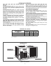
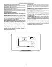
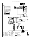
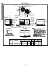
TYPICAL WIRING SCHEMATICS
569D090, 208/230-3-360 and 460-3-60 Units
NOTES:
1. If any of the original wire furnished must be
replaced, it must be replaced with type 90° C
wire or its equivalent.
2. Thermostat: HH07AT170, 172, 174 & P272-
2783
Subbase:HH93AZ176,178 & P272-1882,1883
or HH93AZ177 & 179.
3. Sealed VA for IFC and LLSV is not to exceed
22.
4. Use copper conductors only.
5. TRAN is wired for 230 v unit. If unit is to be run
with 200 v power supply, disconnect BLK wire
from 230 v tapand connect to 200v tap.
6. If TRAN is wired for 460-3-60 v and unit is tobe
run with 400-3-50 v power supply, disconnect
BLK wire from 460 v tap and connect to 400 v
tap.
7. Three-phase motors are protected under pri-
mary single phasing conditions.
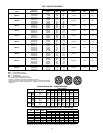
VOLTAGE
RATING
CB MUST
TRIP
AMPS
Mfg. Part No.
24 V
Potter & Brumfield
3.2
W28X-1024-3.2
AHA — Adjustable Heat Anticipator
C—Contactor, Compressor
CAP — Capacitor
CB — Circuit Breaker
CC — Cooling Compensator
CH — Crankcase Heater
CLO — Compressor Lockout
COMP — Compressor Motor
DGT — Discharge Gas Thermostat
EQUIP — Equipment
GND — Ground
HPS — High-Pressure Switch
IFC — Indoor-FanContactor
LLSV — Liquid Line Solenoid Valve
LPS — Low-Pressure Switch
NEC — National Electrical Code
OFM — Outdoor-Fan Motor
QT — Quadruple Terminal
TB — Terminal Block
TC — Thermostat-Cooling
TH — Thermostat-Heating
TRAN — Transformer
Field Splice
Marked Wire
Terminal (Marked)
Terminal (Unmarked)
Terminal Block
Splice
Factory Wiring
—— Field Control Wiring
Field Power Wiring
Accessory or Optional Wiring
To Indicate Common Potential
Only, Not Represent Wiring
LEGEND