


8
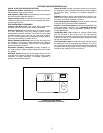
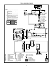
CONTROLS
OPERATING SEQUENCES
569D072-120, 576C120 — At start-up, the thermostat calls for
cooling. With all safety devices satisfied, the compressor
contactor and fan contactor energize, causing the compressor
and outdoor-fan motor to operate. Thermostat contacts
energize, allowing the field-supplied and field-installed indoor-
fan contactor to function. A field-supplied and field-installed liq-
uid line valve also opens, allowing the system to function in
Cooling mode. As cooling demand is satisfied, the thermostat
contacts break, deenergizing the contactor and causing the
system to shut off. The liquid line solenoid valve closes, mini-
mizing the potential for refrigerant migration. The compressor
does not restart until the thermostat again calls for cooling. The
system is protected with a safety circuit so that the system will
not start if a fault exists (i.e., high or low pressure fault). To reset
the safety circuit, set the thermostat to eliminate the cooling
demand, then return to original set point. This should be done
only once, and if system shuts down due to the same fault,
determine the problem before attempting to restart the system.
566D150-240 — When the first stage of cooling thermostat
closes, the timer starts. After approximately 3 seconds, the
timer activates the compressor and fan motor no. 1 contactors.
When the liquid pressure builds to approximately 257 psig, fan
motor no. 2 is energized.
When there is demand for additional cooling capacity, the
second stage of the cooling thermostat closes, energizing a
field-supplied liquid line solenoid (LLS) valve, which opens. This
increases the suction pressure, causing the compressor to
operate at higher capacity (compressor loads).
When the fan switch is set at AUTO, the indoor-air fan cycles
with the compressor. When the switch is set at CONT, the
indoor-air fan runs continuously.
At shutdown, the Time Guard II timer prevents the compressor
from restarting for approximately 5 minutes.
In addition, an LLS valve wired in parallel with the compressor
contactor coil shuts off the liquid line to prevent refrigerant
migration back to the compressor during the off cycle.
569F120 — When the thermostat calls for stage one cooling at
start-up, and all safety devices are satisfied, the compressor
contactor no. 1 (C1) energizes causing compressor no. 1 and
outdoor-fan motor no. 1 to start (the indoor-fan contactor should
be wired to start at the same time as the compressor). The
liquid line solenoid (LLS) valve will open when compressor no. 1
starts, allowing refrigerant to flow in the system.
When the thermostat calls for stage two cooling, compressor
contactor no. 2 (C2) energizes causing compressor no. 2 and
outdoor-fan motor no. 2 to start. As the cooling demand
decreases, stage two on the thermostat opens, causing
compressor no. 2 and outdoor-fan motor no. 2 to shut down. As
the cooling continues to decrease, stage one of the thermostat
opens causing compressor no. 1 and outdoor-fan motor no. 1 to
shut down. The LLS valve for each compressor will close when
the associated compressor stops, minimizing the potential for
refrigerant migration during the off cycle.
The indoor-fan motor will stop if the thermostat is set to AUTO
and will continue to operate if the thermostat is set to CONT.
Each compressor is protected with a Cycle-LOC
TM
device so
that the compressor will not operate if there is a high-pressure
fault, low pressure fault, or a compressor is off due to internal
line break overcurrent/overtemperature protection. To reset the
Cycle-LOC device, set the thermostat higher to remove the
cooling demand, then return to the original set point. This
should be done only once. If the system shuts down with the
same fault, the cause for the fault should be determined and
corrected before the a Cycle-LOC device is reset again.
566E150-240 — At start-up, when the thermostat calls for first
stage cooling and all safety devices are satisfied, the compres-
sor contactor (C1) energizes causing compressor no. 1 and fan
motor no. 1 to start. Fan motor no. 2 will start when the fan
cycling pressure switch (FCPS) closes as discharge pressure
builds (refer to physical data table for FCPS specifications).
With the indoor-fan contactor wired to TB2-4 and TB2-9
contacts on the terminal block, the indoor fan will also start with
the compressor. The liquid line solenoid (LLS) valve will open
when compressor no. 1 starts, allowing refrigerant to flow in the
system.
When the thermostat calls for stage two cooling, compressor
contactor no. 2 (C2) energizes causing compressor no. 2 to
start. As the cooling demand decreases, stage two on the
thermostat opens, causing compressor no. 2 to shut down. As
the cooling continues to decrease, stage one of the thermostat
opens causing compressor no. 1 and outdoor-fan motor to shut
down. The LLS valve for each compressor will close when the
associated compressor stops, minimizing the potential for
refrigerant migration during the off cycle.
The indoor-fan motor will stop if the thermostat is set to AUTO
and will continue to operate if the thermostat is set on CONT.
Each compressor is controlled by the thermostat so they will not
start until there is a demand from the thermostat. Each
compressor is protected with a Cycle-LOC device so that the
compressor will not operate if there is a high-pressure fault,
low-pressure fault, or compressor is off due to internal line
break overcurrent/overtemperature protection. To reset the a
Cycle-LOC device, set the thermostat higher to remove the
cooling demand, then return to the original set point. This
should be done only once. If the system shuts down with the
same fault, the cause for the fault should be determined and
corrected before the a Cycle-LOC device is reset again.