


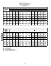

60
GUIDE SPECIFICATIONS — 566D150-240, 566E150-240 (cont)
Manual reset at the unit
Electrical overload protection through the use of def-
inite-purpose contactors and calibrated, ambient
compensated, magnetic trip circuit breakers. Circuit
breakers shall open all 3 phases in the event of an
overload in any one of the phases or a single-phase
condition.
H. Operating Characteristics:
1. The capacity of the condensing unit shall meet or
exceed_____Btuh at a suction temperature of_____ F.
The power consumption at full load shall not
exceed_____ kW.
2. The combination of the condensing unit and the
evaporator or fan coil unit shall have a total net cool-
ing capacity of _____ Btuh or greater at conditions of
_____ cfm entering-air temperature at the evaporator
at _____ F wet bulb and _____ F dry bulb, and air
entering the condensing unit at _____ F.
3. The system shall have an EER of _____ Btuh/Watt or
greater at standard ARI conditions.
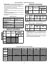
I. Electrical Requirements:
1. Nominal unit electrical characteristics shall be _____ v,
3-ph, 60 Hz. The unit shall be capable of satisfactory
operation within voltage limits of _____ v to _____ v.
2. Unit electrical power shall be single point connection.
3. Unit control circuit shall contain a 24-v transformer
for unit control, with capacity to operate an indoor fan
interlock.
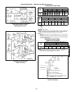
J. Special Features:
1. Low-Ambient Temperature Control (Factory-Installed
Option or Field-Installed Accessory):
Control shall regulate fan motor speed in response
to the saturated condensing temperature of the unit.
The control shall allow the unit to operate down to an
ambient temperature of –20 F.
2. Electric Solenoid Unloader Accessory:
Unloader valve piston, coil, and hardware shall be
supplied to convert the pressure-operated compres-
sor unloader to electric unloading.
3. Hail Guard Package:
Hail guard package shall protect coil against hail and
other flying debris.
4. Condenser Coil Grille Package:
Grilles shall protect the condenser coils after unit
installation.
5. Optional Condenser Coil Materials:
a. Pre-Coated Aluminum-Fin Coils:
Shall have a durable epoxy-phenolic coating to
provide protection in mildly corrosive coastal envi-
ronments. Coating shall be applied to the alumi-
num fin stock prior to the fin stamping process to
create an inert barrier between the aluminum fin
and copper tube. Epoxy-phenolic barrier shall
minimize galvanic action between dissimilar
metals.
b. E-Coated Aluminum-Fin Coils:
Shall have a flexible epoxy polymer coating uni-
formly applied to all coil surface areas without
material bridging between fins. Coating process
shall ensure complete coil encapsulation. Color
shall be high gloss black with gloss requirements
of 60° of 65-90% per ASTM D523-89. Uniform dry
film thickness from 0.8 to 1.2 mil on all surface
areas including fin edges. Superior hardness
characteristics of 2H per ASTM D3363-92A and
cross hatch adhesion of 4B-5B per ASTM D3359-
93. Impact resistance shall be up to 160 in./lb
(ASTM D2794-93). Humidity and water immersion
resistance shall be up to a minimum of 1000 and
250 hours respectively (ASTM-D2247-92 and
ASTM D870-92). Corrosion durability shall be
confirmed through testing to no less than 1000
hours salt spray per ASTM B117-90. Coil con-
struction shall be aluminum-fins mechanically
bonded to copper tubes.
6. Thermostat Control Accessory:
a. Commercial Electronic Thermostat with 7-day
timeclock, auto-changeover, multi-stage capabil-
ity, and large LCD temperature display.
b. Commercial Electronic Non-programmable Ther-
mostat with auto-changeover, multi-stage capabil-
ity, and large LCD temperature display.
7. Unit-Mounted, Non-Fused Disconnect Switch:
Shall be factory-installed, internally mounted. NEC
and UL approved non-fused switch shall provide unit
power shutoff. Shall be accessible from outside the
unit and shall provide power off lockout capability.
Not to be used when rooftop electrical rating
exceeds 80 amperes.
8. Convenience Outlet:
Shall be factory-installed and internally mounted
with easily accessible 115-v female receptacle. Shall
include 15 amp GFI receptacle with independent
fuse protection. Voltage required to operate conve-
nience outlet shall be provided by a factory-installed
step-down transformer. Shall be accessible from out-
side the unit.
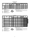
50TFQ004-012
566D/E150-240