


106
GUIDE SPECIFICATIONS — SIZES 036-150
PACKAGED ROOFTOP COOLING UNIT WITH ELECTRIC
HEAT OPTION — CONSTANT VOLUME APPLICATION
HVAC GUIDE SPECIFICATIONS
SIZE RANGE: 3 to 12
1
/
2
TONS, NOMINAL COOLING
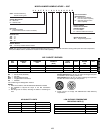
BRYANT MODEL NUMBER:
558F, 551B
PART 1 — GENERAL
1.01 SYSTEM DESCRIPTION
Outdoor rooftop- or slab-mounted, electrically controlled
cooling unit with optional heat utilizing either reciprocating
(558F) or scroll compressors for cooling duty and electric
resistance coils for heating duty. Unit shall discharge sup-
ply air vertically or horizontally as shown on contract
drawings.
1.02 QUALITY ASSURANCE
A. Unit shall be rated in accordance with ARI Standards 210/
240 or 360 and 270.
B. Unit shall be designed to conform to ASHRAE 15, latest
revision, and in accordance with UL 1995.
C. Unit shall be UL tested and certified in accordance with
ANSI Z21.47 Standard and UL listed and certified under
Canadian Standards as a total package for safety
requirements.
D. Roof curb shall be designed to conform to NRCA
Standards.
E. Insulation and adhesive shall meet NFPA 90A require-
ments for flame spread and smoke generation.
F. Unit casing shall be capable of exceeding Federal Test
Method Standard No. 141 (Method 6061) 500-Hour Salt
Spray Test.
G. Each unit is subjected to completely automated run test-
ing on the assembly line. Each unit contains a factory-
supplied printout indicating tested pressures, amperages,
data, and inspectors; providing certification of the unit
status at the time of manufacture.
1.03 DELIVERY, STORAGE, AND HANDLING
Unit(s) shall be stored and handled per manufacturer’s
recommendations.
PART 2 — PRODUCTS
2.01 EQUIPMENT (STANDARD)
A. General:
Factory-assembled, single-piece cooling unit with
optional heat. Contained within the unit enclosure shall be
all factory wiring, piping, controls, refrigerant charge
(R-22), and special features required prior to field
start-up.
B. Unit Cabinet:
1. Unit cabinet shall be constructed of galvanized steel,
bonderized and coated with a baked enamel finish
on all externally exposed surfaces, and have primer-
coated interior panel surfaces.
2. Evaporator fan cabinet interior shall be insulated with
a minimum
1
/
2
-in. thick flexible fiberglass insulation
coated on the air side.
3. Cabinet panels shall be easily removable for
servicing.
4. Holes shall be provided in the base rails for rigging
shackles to facilitate overhead rigging, and forklift
slots shall be provided to facilitate maneuvering.
5. Unit shall have a factory-installed, sloped conden-
sate drain pan made of a non-corrosive material,
providing a minimum
3
/
4
-in. connection with both
vertical and horizontal drains and shall comply with
ASHRAE 62.
6. Unit shall have factory-installed filter access panel to
provide filter access with tool-less removal.
7. Unit shall have standard thru-the-bottom power con-
nection capability.
C. Fans:
1. Indoor blower (evaporator fan) shall be of the belt-
driven, double inlet, forward-curved centrifugal type.
Belt drive shall include an adjustable-pitch motor
pulley (558F072-150, 551B036-150).
2. Indoor blower (evaporator fan) shall be made from
steel with a corrosion-resistant finish and shall be
dynamically balanced.
3. Bearings shall be of the sealed, permanently lubri-
cated, ball-bearing type for longer life and lower
maintenance.
4. Condenser fan shall be of the direct-driven propeller
type and shall discharge air vertically.
5. Condenser fan shall have blades riveted to corrosion-
resistant steel spiders and shall be dynamically
balanced.
6. Condenser-fan motor shall be totally enclosed.
D. Compressor(s):
1. Scroll type (reciprocating type, 558F), internally
protected.
2. Factory rubber-shock mounted and internally spring
mounted for vibration isolation.
3. On independent circuits (090-150).
E. Coils:
1. Evaporator and condenser coils shall have aluminum
plate fins mechanically bonded to enhanced copper
tubes with all joints brazed.
2. Tube sheet openings shall be belled to prevent tube
wear.
3. Evaporator coil shall be of the face-split design
(090-150).
F. Refrigerant Components:
Refrigerant circuit components shall include:
1. Fixed orifice metering feed system.
2. Refrigerant filter drier.
3. Service gage connections on suction, discharge, and
liquid lines.
4. Ability to route gage hoses through unit top cover or
outdoor panel.
G. Filter Section:
1. Standard filter section shall consist of factory-
installed low-velocity, throwaway 2-in. thick fiberglass
filters of commercially available sizes.
2. Filter face velocity shall not exceed 320 fpm at nomi-
nal airflows.
3. Filter section shall use only one size filter.
4. Filters shall be accessible through an access panel
with “no-tool” removal.
H. Controls and Safeties:
1. Unit Controls:
Unit shall be complete with self-contained low-volt-
age control circuit protected by a fuse on the 24-v
transformer side.
50TFQ004-012
558F/551B036-150