


—20—
Once base ventilation has been determined, set the mini-
mum damper position potentiometer to the correct position.
The same equation can be used to determine the occupied or
maximum ventilation rate to the building. For example, an
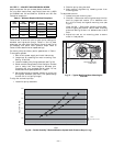
output of 3.6 volts to the actuator provides a base ventilation
rate of 5% and an output of 6.7 volts provides the maximum
ventilation rate of 20% (or base plus 15 cfm per person). Use
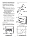
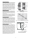
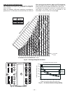
Fig. 35 to determine the maximum setting of the CO
2
sensor.
For example, a 1100 ppm set point relates to a 15 cfm per
person design. Use the 1100 ppm curve on Fig. 35 to find the
point when the CO
2
sensor output will be 6.7 volts. Line up
the point on the graph with the left side of the chart to deter-
mine that the range configuration for the CO
2
sensor should
be 1800 ppm. The EconoMi$er IV controller will output the
6.7 volts from the CO
2
sensor to the actuator when the CO
2
concentration in the space is at 1100 ppm. The DCV set point
may be left at 2 volts since the CO
2
sensor voltage will be
ignored by the EconoMi$er IV controller until it rises above
the 3.6 volt setting of the minimum position potentiometer.
Once the fully occupied damper position has been deter-
mined, set the maximum damper demand control ventilation
potentiometer to this position. Do not set to the maximum
position as this can result in over-ventilation to the space
and potential high-humidity levels.
CO
2
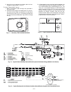
Sensor Configuration
The CO
2
sensor has preset standard voltage settings that
can be selected anytime after the sensor is powered up. See
Table 7.
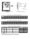
Use setting 1 or 2 for Bryant equipment. See Table 7.
1. Press Clear and Mode buttons. Hold at least 5 sec-
onds until the sensor enters the Edit mode.
2. Press Mode twice. The STDSET Menu will appear.
3. Use the Up/Down button to select the preset number.
See Table 7.
4. Press Enter to lock in the selection.
5. Press Mode to exit and resume normal operation.
The custom settings of the CO
2
sensor can be changed any-
time after the sensor is energized. Follow the steps below to
change the non-standard settings:
1. Press Clear and Mode buttons. Hold at least 5 sec-
onds until the sensor enters the Edit mode.
2. Press Mode twice. The STDSET Menu will appear.
3. Use the Up/Down button to toggle to the NONSTD
menu and press Enter.
4. Use the Up/Down button to toggle through each of
the nine variables, starting with Altitude, until the
desired setting is reached.
5. Press Mode to move through the variables.
6. Press Enter to lock in the selection, then press Mode
to continue to the next variable.
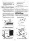
Dehumidification of Fresh Air with DCV Control
Information from ASHRAE indicates that the largest humid-
ity load on any zone is the fresh air introduced. For some
applications, an energy recovery unit is added to reduce the
moisture content of the fresh air being brought into the
building when the enthalpy is high. In most cases, the nor-
mal heating and cooling processes are more than adequate to
remove the humidity loads for most commercial applications.
If normal rooftop heating and cooling operation is not ade-
quate for the outdoor humidity level, an energy recovery unit
and/or a dehumidification option should be considered.
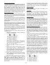
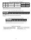
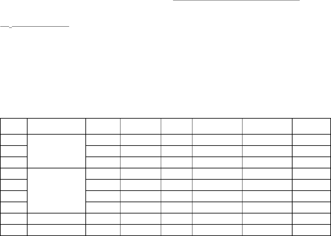
Table 7 — CO
2
Sensor Standard Settings
LEGEND
ppm — Parts Per Million
SETTING EQUIPMENT OUTPUT
VENTILATION
RATE
(cfm/Person)
ANALOG
OUTPUT
CO
2
CONTROL RANGE
(ppm)
OPTIONAL
RELAY SETPOINT
(ppm)
RELAY
HYSTERESIS
(ppm)
1
Interface w/Standard
Building Control System
Proportional Any
0-10V
4-20 mA
0-2000 1000 50
2 Proportional Any
2-10V
7-20 mA
0-2000 1000 50
3 Exponential Any
0-10V
4-20 mA
0-2000 1100 50
4
Economizer
Proportional 15
0-10V
4-20 mA
0-1100 1100 50
5 Proportional 20
0-10V
4-20 mA
0- 900 900 50
6 Exponential 15
0-10V
4-20 mA
0-1100 1100 50
7 Exponential 20
0-10V
4-20 mA
0- 900 900 50
8 Health & Safety Proportional —
0-10V
4-20 mA
0-9999 5000 500
9
Parking/Air Intakes/
Loading Docks
Proportional —
0-10V
4-20 mA
0-2000 700 50