


—2—
III. STEP 3 — INSTALL CONDENSATE DRAIN LINE AND
EXTERNAL TRAP
Condensate drain connections are located at the bottom and
end of the unit. Unit discharge connections do not determine
the use of drain connections; either drain connection can be
used in vertical or horizontal applications.
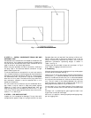
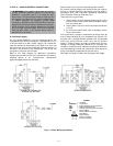
When using the standard end drain connection, make sure
the plug (red) in the alternate bottom connection is tight
before installing the unit.
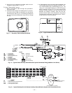
To use the bottom drain connection for a roof curb installa-
tion, relocate the factory-installed plug (red) from the bottom
connection to the end connection. See Fig. 4. The piping for
the condensate drain and external trap can be completed
after the unit is in place. The center drain plug looks like a
star connection, however it can be removed with a
1
/
2
-in.
socket drive extension.
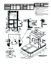
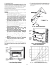
All units must have an external trap for condensate drain-
age. Install a trap at least 4-in. deep and protect against
freeze-up. If drain line is installed downstream from the
external trap, pitch the line away from the unit at 1 in. per
10 ft of run. Do not use a pipe size smaller than the unit con-
nection (
3
/
4
in.). See Fig. 5.
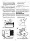
IV. STEP 4 — RIG AND PLACE UNIT
Inspect unit for transportation damage. File any claim with
transportation agency. Keep unit upright and do not drop.
Spreader bars are not required if top crating is left on unit.
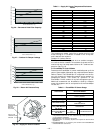
Rollers may be used to move unit across a roof. Level by
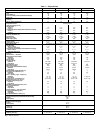
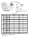
using unit frame as a reference. See Table 1 and Fig. 6 for
additional information. Operating weight is shown in
Table 1 and Fig. 6.
Lifting holes are provided in base rails as shown in Fig. 6
and 7. Refer to rigging instructions on unit.
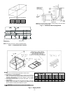
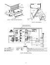
A. Positioning
Maintain clearance around and above unit to provide proper
airflow and service access. See Fig. 7.
Position unit on roof curb so that the following clearances are
maintained:
1
/
4
in. clearance between the roof curb and the
base rail inside the front and rear, 0.0 in. clearance between
the roof curb and the base rail inside on the duct end of the
unit. This will result in the distance between the roof curb
and the base rail inside on the condenser end of the unit
being approximately equal to Fig. 2, section C-C.
Do not install unit in an indoor location. Do not locate unit
air inlet near exhaust vents or other sources of contaminated
air.
Although unit is weatherproof, guard against water from
higher level runoff and overhangs.
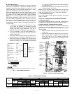
After unit is in position, remove polyethylene shipping wrap-
per and rigging skid.
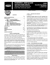
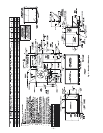
Fig. 1 — Horizontal Conversion Panels