


—11—
B. Field Control Wiring
Install a Bryant-approved accessory thermostat assembly
according to installation instructions included with the
accessory. Locate thermostat assembly on a solid wall in the
conditioned space to sense average temperature in accor-
dance with thermostat installation instructions.
Route thermostat cable or equivalent single leads of colored
wire from subbase terminals to low-voltage connections on
unit (shown in Fig. 9) as described in Steps 1 through 4 below.
NOTE: For wire runs up to 50 ft, use no. 18 AWG (American
Wire Gage) insulated wire (35 C minimum). For 51 to 75 ft,
use no. 16 AWG insulated wire (35 C minimum). For over
75 ft, use no. 14 AWG insulated wire (35 C minimum). All
wire larger than no. 18 AWG cannot be directly connected to
the thermostat and will require a junction box and splice at
the thermostat.
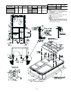
1. If mounted on a roof curb and electrical power is to be
run through the basepan, an accessory thru-the-
bottom connection kit is required. This is available
through the local Bryant distributor. This kit is
required to ensure a reliable water-tight connection.
2. If unit is mounted on roof curb and accessory thru-
the-bottom service connections are used, route wire
through connections.
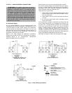
3. Pass control wires through the hole provided on unit
(see connection D in Connection Sizes table in Fig. 7).
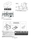
4. Feed wire through the raceway built into the corner
post to the 24-v barrier located on the left side of the
control box. See Fig. 9. The raceway provides the
UL required clearance between the high-voltage and
low-voltage wiring.
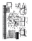
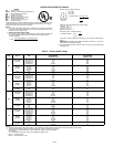
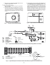
5. Connect thermostat wires to screw terminals of low-
voltage connector (see Fig. 9).
NOTE: If thru-the-bottom power connections are used refer
to the accessory installation instructions for information on
power wiring. Refer to Fig. 7 for drilling holes in basepan.
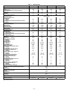
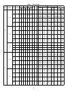
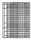
C. Heat Anticipator Settings
For units with electric heat, set heat anticipator settings as
shown in Table 4.
VI. STEP 6 — ADJUST FACTORY-INSTALLED OPTIONS
A. Disconnect Switch
The optional disconnect switch is non-fused. The switch has
the capability of being locked in place for safety purposes.
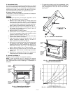
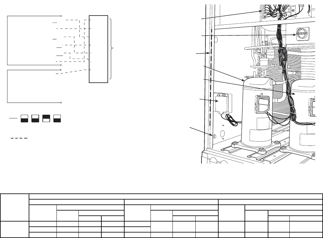
B. Perfect Humidity™ Dehumidification System
Perfect Humidity system operation can be controlled by field
installation of a Bryant-approved humidistat (Fig. 11), or
light commercial Thermidistat™ device (Fig. 12). To install
the humidistat:
1. Route humidistat cable through hole provided in unit
corner post.
2. Feed wires through the raceway built into the corner
post to the 24-v barrier located on the left side of the
control box. See Fig. 10. The raceway provides the
UL-required clearance between high-voltage and low-
voltage wiring.
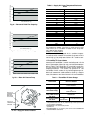
Table 4 — Heat Anticipator Settings
*Heater capacity (kW) is based on heater voltage of 208 v, 240 v, 480 v or 575 v. If power distribution voltage to unit varies from rated heater voltage,
heater kW will vary accordingly.
UNIT
UNIT VOLTAGE
208/230 460 575
Heater
kW*
Configuration
Heater
kW
Configuration
Heater
kW
Configuration
1-Stage
2-Stage
1-Stage
2-Stage
1-Stage
2-Stage
Stage 1 Stage 2 Stage 1 Stage 2 Stage 1 Stage 2
551B
10.4, 16.0 0.3 NA NA 13.9, 16.5
0.3 NA NA 17.0, 34.0 0.3 NA NA
24.8, 32.0 0.6 0.3 0.3 27.8, 33.0
42.4, 50.0 0.9 0.6 0.3 41.7, 50.0 0.6 0.3 0.3 51.0 0.6 0.3 0.3
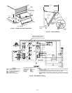
CONNECTION
BOARD
FACTORY-
INSTALLED
DISCONNECT
(OPTION)
RACEWAY
COMPRESSOR
NO. 2
COMPRESSOR
NO. 1
CONVENIENCE
OUTLET
(OPTION)
HOLE IN
END
PANEL
Fig. 10 — Field Control Wiring Raceway
WIRE
CONNECTIONS
TO
LOW-VOLTAGE
SECTION
(CONNECTION
BOARD)
COOL STAGE 1
FAN
HEAT STAGE 1
COOL STAGE 2
HEAT STAGE 2
24 VAC HOT
24 VAC COM
N/A
OUTDOOR AIR
SENSOR
Y1/W2
G
W/W1
Y/Y2
O/W2
R
C
S1
S2
THERMOSTAT DIPSWITCH SETTINGS
R
G
Y1
Y2
W1
W2
C
IPD/X
ON
OFF
A
B
C
D
LEGEND
NOTE: Underlined letter indicates active thermostat output when configured
for A/C operation.
Fig. 9 — Low-Voltage Connections
Field Wiring