


3
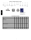
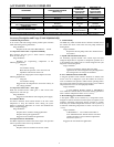
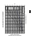
PHYSICAL DATA
UNIT SIZE SERIES 018---B 024---B 030---B 036---B 042---B 048 ---B 060---B
Operating Weight (lb) 198 244 280 299 318 325 307
Shipping Weight (lb) 232 280 310 335 354 361 344
Compressor Type Scroll
REFRIGERANT Puron (R---410A)
Control TXV (Puron Hard Shutoff)
Charge (lb) 6.13 10.4 12 14.8 14.2 12.6 12.5
COND FAN Propeller Type, Direct Drive
Air Discharge Vertical
Air Qty (CFM) 2595 2595 3265 3265 3265 3673 3673
Motor HP 1/10 1/10 1/5 1/5 1/5 1/4 1/4
Motor RPM 800 800 800 800 800 800 800
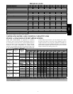
COND COIL
Face Area (Sq ft) 16.26 18.3 20.33 24.4 24.4 24.4 22.4
Fins per In. 20 20 20 20 20 20 20
Rows 1 1 1 2 2 2 2
Circuits 4 5 6 5 7 8 9
VALVECONNECT.(In.ID)
Vapor 5/8” 5/8” 3/4” 3/4” 7/8” 7/8” 7/8”
Liquid 3/8”
REFRIGERANT TUBES* (In. OD)
Vapor (0---80 Ft Tube Leng th) 5/8” 5/8” 3/4” 3/4” 7/8” 7/8” 1---1/8”
Liquid (0---80 Ft Tube Lengt h) 3/8”
* For tubing sets between 80 ft. and 200 ft. horizontal or 20 ft. vertical differential (250 ft. Total Equivalent Length), consult the Long---Line Guideline.
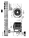
Note: See unit Installation Instruction for proper installation.
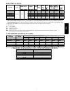
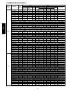
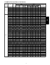
VAPOR LINE SIZING AND COOLING CAPACI TY LOSS
PURON 1--STAGE HEAT PUMP APPLICATIONS
LONG LINE APPLICATION: An application is considered
”Long line” when the total equivalent tubing length exceeds 80
ft. or whe n there is more than 20 ft. vertical separation between
indoor and outdoor units. These applications require additional
accessories and system modifications fo r reliable system
operation. The maximum allowable total equivalent length is 250
ft. The maximum vertical separation is 200 ft. when outdoor unit
is above indoor unit, and 80 ft. when the outdoor unit is below
the indoor unit. Refer to Accessory Usage Guideline below for
required accessories. See Long--Line Application Guideline for
required piping and system modifications. Also, refer to the table
below for the acceptable vapor tube diameters based on the total
length to minimize the cooling capacity loss.
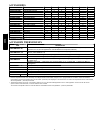
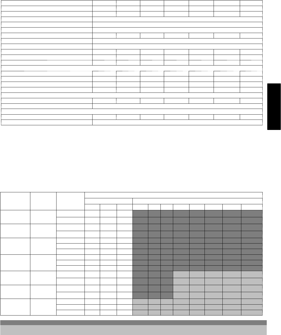
Unit Nominal
Size (Btuh)
Acceptable
LiquidLine
Diameter OD
(in.)
Acceptable
Vapor Line
Diameters
OD (in.)
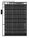
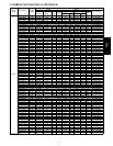
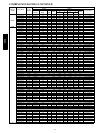
Cooling Capacity Loss (%)Total Equivalent Line Length (ft.)
Standard Application Long Line Application Requires Accessories
25 50 80 80+ 100 125 150 175 200 225 250
18000
1---Stage Puron
HP
3/8
1/2 1 2 3 3 4 6 7 8 9 10 12
5/8 0 0 1 1 1 1 2 2 3 3 3
24000
1---Stage Puron
HP
3/8
5/8 0 1 1 1 2 3 3 4 4 5 6
3/4 0 0 0 0 0 1 1 1 1 1 2
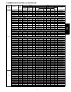
30000
1---Stage Puron
HP
3/8
5/8 1 2 3 3 3 4 5 6 7 8 9
3/4 0 0 1 1 1 1 2 2 2 3 3
7/8 0 0 0 0 0 1 1 1 1 1 1
36000
1---Stage Puron
HP
3/8
5/8 1 2 4 4 5 6 7 9 10 11 13
3/4 0 0 1 1 1 2 2 3 3 4 4
7/8 0 0 0 0 0 1 1 1 1 2 2
42000
1---Stage Puron
HP
3/8
3/4 0 1 2 2 2 3 4 4 5 6 6
7/8 0 0 1 1 1 1 2 2 2 3 3
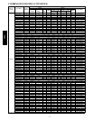
48000
1---Stage Puron
HP
3/8
3/4 0 1 2 2 3 4 5 5 6 7 8
7/8 0 0 1 1 1 2 2 2 3 3 4
60000
1---Stage Puron
HP
3/8
3/4 1 2 4 4 5 6 7 9 10 11 12
7/8 0 1 2 2 2 3 4 4 5 5 6
11/8 0 0 0 0 1 1 1 1 1 1 2
Standard Length = 80 ft. or less total equivalent length
Applications in this area are long line. Accessories are required as shown recommended on Long Line Application Guidelines
Applications in this area may have height restrictions that limit allowable total equivalent length, when outdoor unit is below indoor unit See
Long Line Application Guidelines
265A