


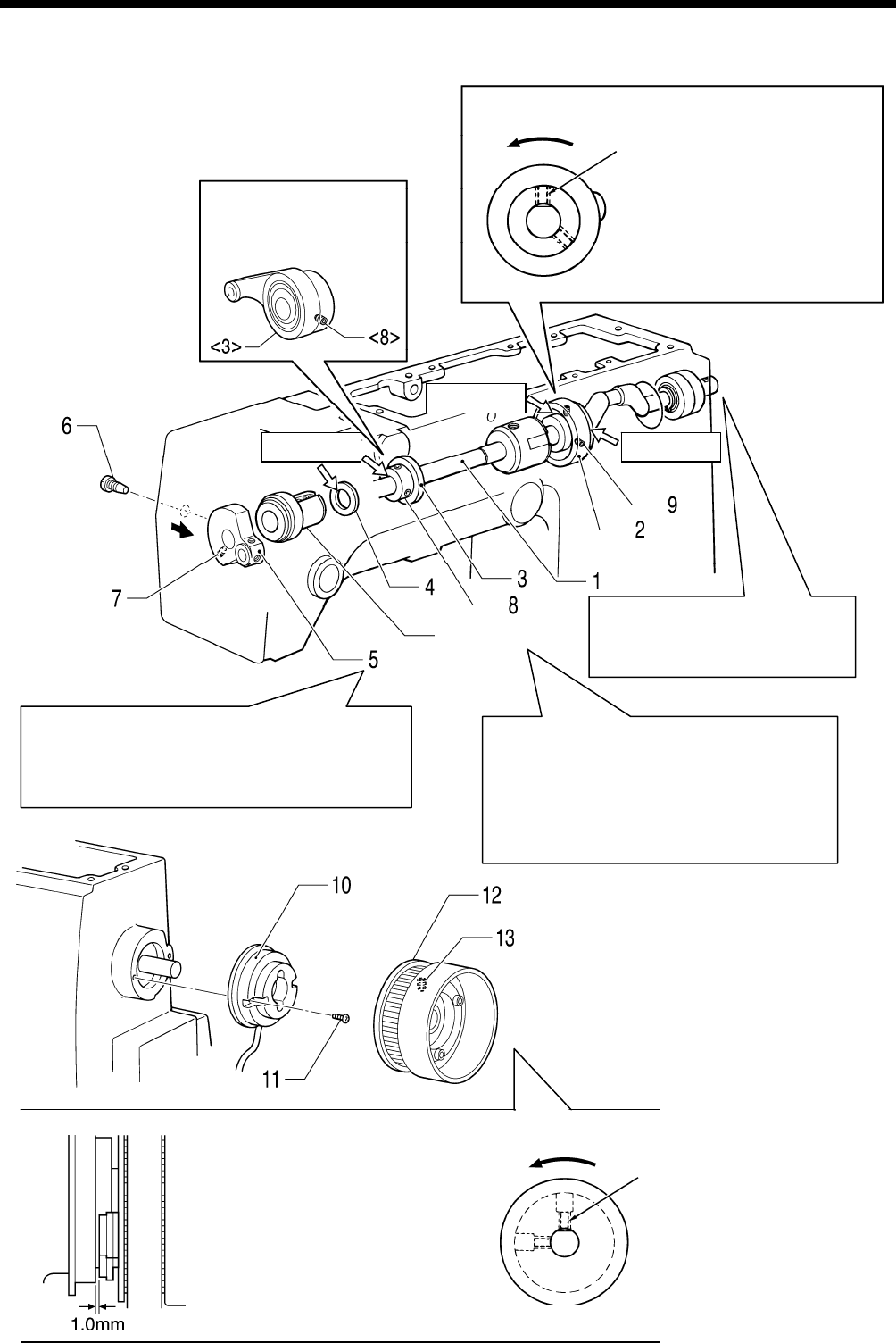
4. ASSEMBLY
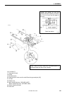
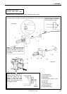
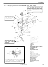
4-8. Upper shaft mechanism
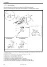
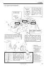
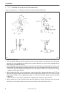
Push the t
hread trimmer
cam onto the upper shaft
crank, align the forward set
screw in the rotation
direction with the screw
stop position, and tighten
the set screw at that
position.
Rotation direction
<KE-435B, 435C>
<
KE-436B, 436C>
3380Q
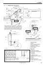
Apply grease.
Apply grease. Apply grease.
Apply adhesive (Threebond
14
01 or similar) to the outside
of the bearing.
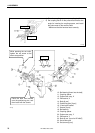
Upper shaft bu
sh
KE-430B, 430C series
76
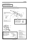
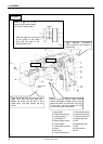
Make a gap of 1.0 mm between
the magnet of timing pulley
assembly U and the syn-
chronizer assembly, and then
align the rear set screw in the
rotation direction of timing pulley
assembly U with the screw stop
position and tighten the set
screw at that position.
Rotation direction
3382Q
3383Q
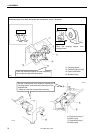
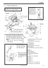
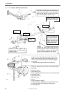
Place the thread take-up crank onto the upper
shaft from the face plate end, tighten the
screw into the hole in the upper shaft, and
then tighten the set screw.
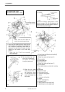
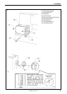
Place the thread take-up crank, thrust
wa
sher and bobbin winder pulley
(stepping foot connecting rod) into the
upper shaft bush so that there is no play
in the parts, and then tighten the set
screw at the screw stop position.
1. Upper shaft
2. Thread trimmer cam
3. Bobbin winder pulley
<3> Stepping foot
connecting rod
4.
Thrust washer
3381Q
5. Th
read take-up crank
6. Screw
7. Set
screw
8.
Set screws [2 pcs]
<8> Set screws [2 pcs]
9. Set screws [2 pcs
10. Synchronizer assy
11. Screws [2 pcs]
12. Timing pulley assy, U
13. Set screws [2 pcs]