


4. ASSEMBLY
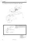
KE-430B, 430C series
75
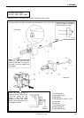
KE-434B, 435B, 436B
KE-434C, 4
35C, 436C, 484C
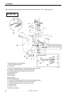
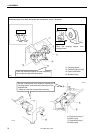
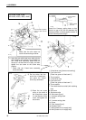
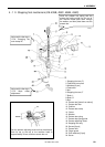
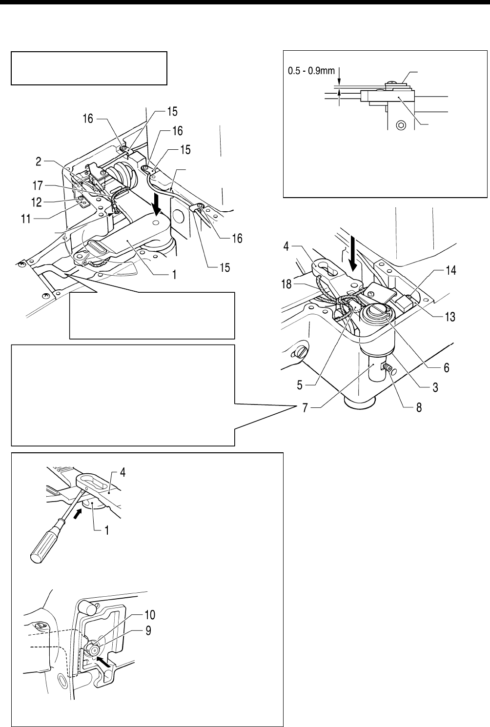
Note:
Make sure the wick does not
touch the connecting rod lever.
Push the home position
sensor Y cable into the
recess.
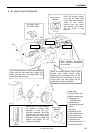
Oil supply
hole
3377Q
Home position
sensor X
Home position
dog, X
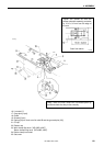
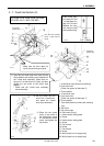
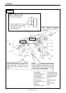
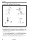
1) Insert the tack width feed lever shaft with the
thrust washer and retaining ring installed into
the Y-feed lever assembly, press down on
the top of it so that there is no play, and then
tighten the set screw at the screw stop
position.
* Check that the Y-feed lever assembly
moves smoothly.
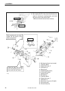
1. X-feed lever assy [Insert onto bushing]
2. Feed cam roller
[Place into groove of feed cam X]
3. Thrust washer
4. Y-feed lever assy
5. Feed cam roller
[Place into groove of feed cam Y]
6. Thrust washer
7. Tack width feed lever shaft (with retaining
ring)
8. Set screw
9. Set screw collar
10. Set screws [2 pcs]
11. X-sensor setting base
12. Screw
13. Y-sensor setting plate
14. Screw
15. Cord clamps [3 pcs]
16. Screws [3 pcs]
17. Wick [Insert into oil supply hole]
18. Wick [Insert into oil supply hole]
3379Q
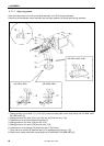
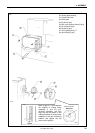
2) Put the driver into the
end of the Y-feed lever,
and press the X-feed
lever assy downward.
3) Place the set screw
collar on the shaft of
the X-feed lever, press
it in the direction of the
arrow, and tighten the
set screws.
3575Q
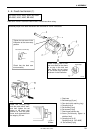
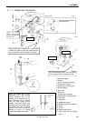
Install the X-sensor setting base so that
there is a gap of 0.5–0.9 mm between the
sensing surface of home position sensor X
and the home position dog X.
3378Q
3376
Q