


8. ELECTRIC MECHANISM
Error status #8 Error code appears on the display window when the foot switch is depressed.
Probable causes Check/ repair/ adjust Parts to be replaced
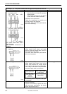
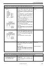
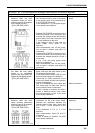
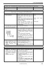
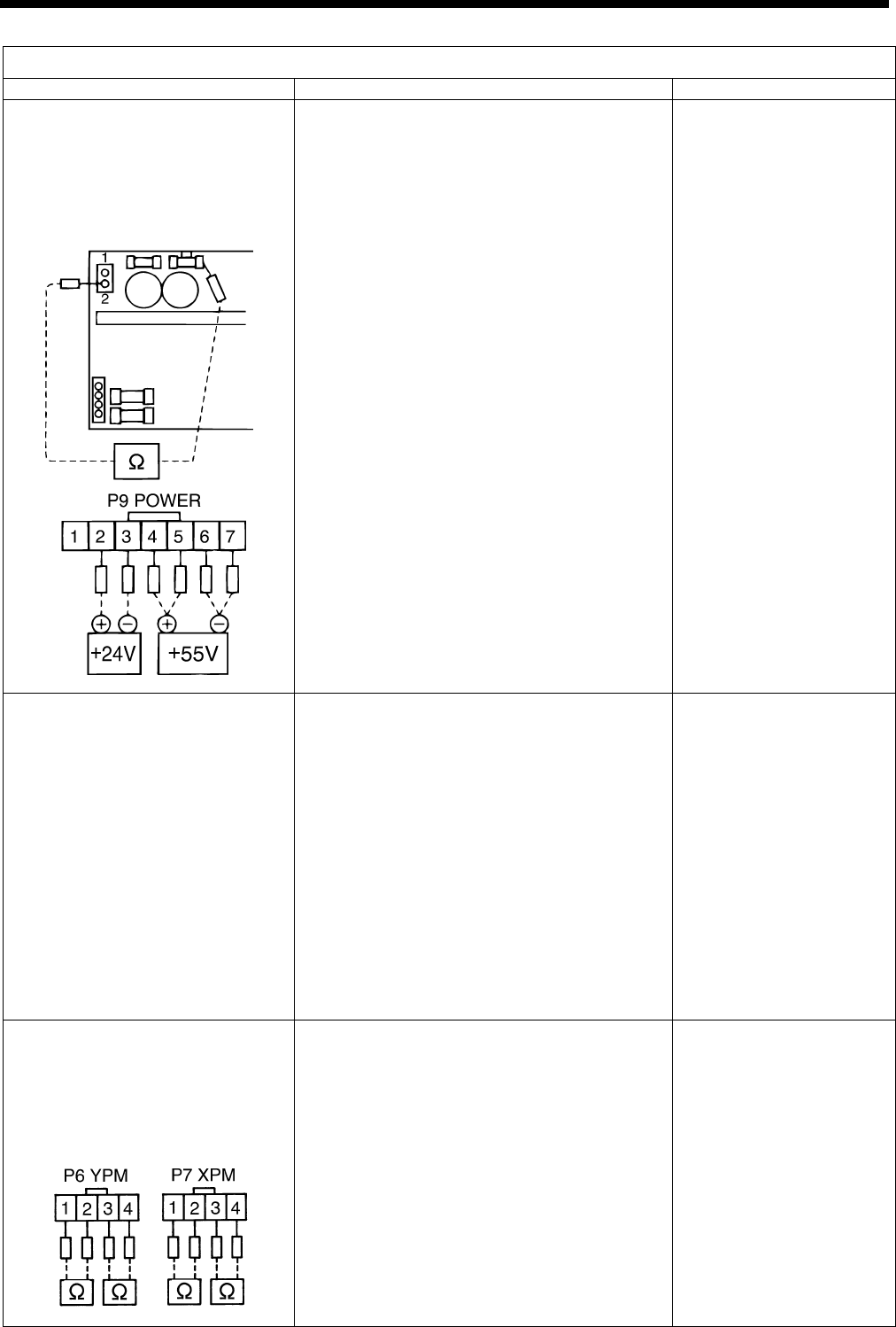
2. Power supply circuit board is
defective when the feed
mechanism does not move
and error code E-A0 appears
on the display window.
([E.A1] KE-436B, 436C)
a. Measure the resistance between the fuse
No.1 terminal which is close to the center
of the power supply circuit board and pin
2 of P5 (DC300) connector.
If the resistance is , the power supply
circuit board is not defective.
b
. Separate P9 (POWER) connectors on the
main circuit board, turn on the power, and
measure the voltage across the following
pairs of pins, pins 4 and 6 and pins 5 and
7, in the connector on the cord.
If the voltage is +55V in each case, the
power supply circuit board is not
defective.
After measurement, turn off the power,
wait at least 5 minutes, and rejoin P9
connectors.
c. Separate P9 (POWER) connectors on the
main circuit board, turn on the power, and
measure the voltage across pins 2 and 3
on the cord.
If it is + 24V, the power supply circuit
board is not defective.
After measurement, turn off the power,
wait at least 5 minutes, and rejoin P9
connectors.
Power supply circuit
board
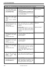
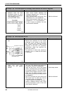
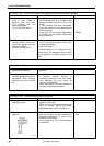
3. Home position sensor is defec-
tive when the work clamp
moves in an unexpected
direction and error code E-A0
appears on the display window.
([E.A1] KE-436B, 436C)
a. Turn the poewr switch off and then on
again, and move the work clamp to near
the home position by hand.
If the home position sensor LED is lit, the
home position sensor is not defective.
b. Check that P1 (ORG) connector on the
main circuit board and the home position
sensor are plugged in.
c. See “8-9. Checking the input sensor and
DIP switch input” to make sure that the
home position sensor is connected.
If item a causes no problem and item b
results in defective sensor input, either
the cord connection is poor or the main
circuit board is defective.
Home position sensor
Main circuit board
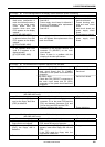
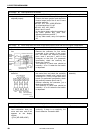
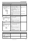
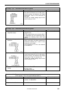
4. Pulse motor and cord are
defective when the work
clamp operates abnormally
and error code E-A0 appears
on the display window.
([E.A1] KE-436B, 436C)
a. Separate P6 (YPM) and P7 (XPM)
connectors on the main circuit board.
Measure the resistance between the
following pairs of pins, pins 4 and 6 and
pins 5 and 7, in the connector on the
cord.
If the resistance is 2–3 , it is not
defective.
After measurement, rejoin P6 and P7
connectors.
b. If item a causes no problem, the main
circuit board is defective.
X- or Y-pulse motor
assembly
Main circuit board
3638Q
3639Q
KE-430B, 430C series
182