


8. ELECTRIC MECHANISM
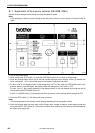
8-9. Checking the input sensor and DIP switch input
[KE-430*, 431*, 432*, 433B, 434*, 435*, 484C, BE-438*]
2581Q
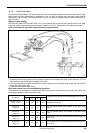
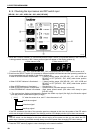
1.
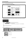
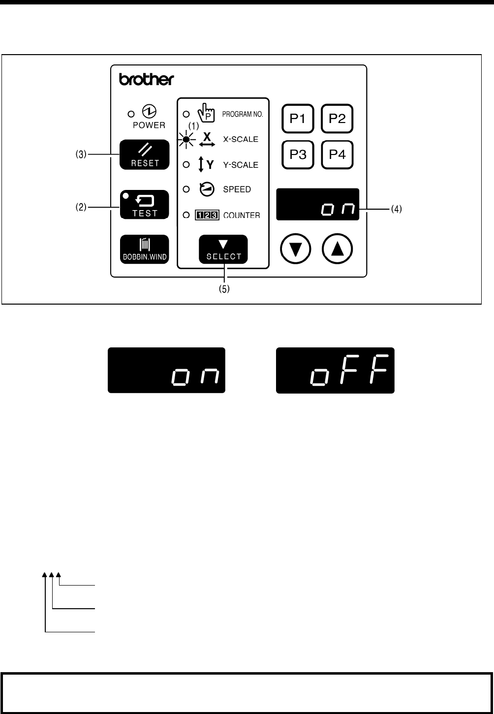
When the X-SCALE indicator (1) is illuminated and the RESET switch (3) is pressed while the TEST switch (2)
is being pressed, the state of the X home position signal will appear on the display window (4).
When sensor is ON When sensor is OFF
KE-430B, 430C series
161
* Fo
r the KE-430*, 431*, 432*, 433B and BE-438*, “ON” is displayed when the Y home position sensor is off.
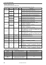
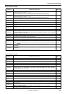
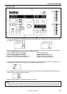
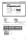
2. Each time the SELECT switch (5) is pressed, a different indicator will illuminate and the operating condition for
the corresponding item will appear on the display window (4).
When X-SCALE indicator is illuminated.......... X home position sensor (ON [KE-430*, 431*, 432*, 433B and
BE-438*] or OFF [KE-434*, 435*, 484C] when home position
detected)
When Y-SCALE indicator is illuminated.......... Y home position sensor (ON [KE-430*, 431*, 432*, 433B and
BE-438*] or OFF [KE-434*, 435*, 484C] when home position
detected)
When SPEED indicator is illuminated.............Synchronizer ( * 1)
When COUNTER indicator is illuminated ....... Presser sensor (ON when presser is lowered)
When PROGRAM NO. indicator is illuminated.....
Work clamp closed sensor (ON when work clamp is open
[KE-432* only])
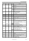
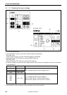
*1 The synchronizer display simultaneously displays the needle up signal (3rd digit), the 24-section signal
(2nd digit) and the needle down signal (1st digit).
[ H L L] “H” when the sensor is on, and “L” when the sensor is off
Needle down signal
24-section signal
Needle up signal
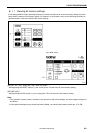
If the DIP switches at the side of the operation panel are changed at this time, the number of the DIP switch
which was changed will be displayed in the 4th digit position of the display window (4) for about one second.
Note:
The DIP switch can be changed at this time without turning off the power so that you can check the DIP
switch input. However, you should normally always turn off the power when changing DIP switch settings.
3. Press the TEST switch (2) again to return the display to the normal condition.