


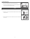

7.1 WHAT YOU NEED TO BALANCE THE UNIT
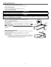
• A magnehelic gauge capable of measuring 0 to 0.5 inch of water (0 to 125 Pa) and
2 plastic tubes.
• The balancing chart located on the unit door.
7.2 PRELIMINARY STAGES TO BALANCE THE UNIT
• Seal all the unit ductwork with tape. Close all windows and doors.
• Turn off all exhaust devices such as range hood, dryer and bathroom fans.
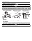
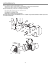
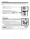
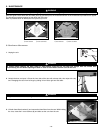
• Make sure the integrated balancing dampers are fully open
. Turn the thumb screw (A) clockwise
to manually open the dampers. Both are located on the Exhaust air to outside port and on Fresh
air to building port.
• Make sure all filters are clean (if it is not the first time you balance the unit).
7.3 B
ALANCING PROCEDURE
1. Set the unit to high speed.
Make sure that the furnace/air handler blower is ON if the installation is in any way connected to
the ductwork of the cold air return. If not, leave furnace/air handler blower OFF. If the outside
temperature is below 0°C / 32°F, make sure the unit is not running in defrost while balancing.
(By waiting 10 minutes after plugging the unit in, you are assured that the unit is not in a
defrost cycle.).
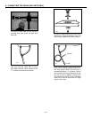
2. Place the magnehelic gauge on a level surface and adjust it to zero.
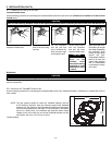
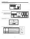
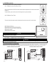
3. Connect tubing from gauge to EXHAUST air flow pressure taps (see diagram beside).
Be sure to connect the tubes to their appropriate
high/low
fittings. If the gauge drops below
zero, reverse the tubing connections.
NOTE: It is suggested to start with the exhaust air flow reading because the exhaust has
typically more restriction than the fresh air, especially in cases of fully ducted
installations or source point ventilation. Place the magnehelic gauge upright and
level. Record equivalent AIR FLOW of the reading according to the balancing chart.
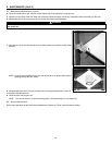
4. Move tubing to FRESH air flow pressure taps (see diagram). Adjust the fresh air balancing damper until the fresh air flow is
approximately the same as the EXHAUST air flow.If fresh air flow is less than exhaust air flow, then go back and adjust the e
xhaust
balancing damper to equal the fresh air flow.
5. Secure both dampers thumb screw in place with tape.
6. Write the required air flow information on a label and stick it near the unit for future reference (date, maximum speed air flows, your
name, phone number and business address).
NOTE: The unit is considered balanced even if there is a difference of ±10 cfm (or ± 5 l/s or 17 m
3
/h) between the two air flows.
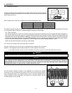
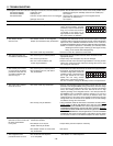
VP0015
1 12 12 11
1 12 12 11
3 13 33 23
1 12 12 11
1 12 12 11
3 13 33 23
Fresh air flow
Balancing
Chart
Exhaust air flow
7. BALANCING THE UNIT
To avoid balancing, the difference between stale air ducts total lenght and fresh air ducts total lenght must not exceed 50 ft. However,
even if the stale air ducts and fresh air ducts lenghts are almost equal, your local building codes may require balancing the unit.
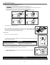
If the unit does not need to be balanced, shut all the pressure taps (located on the unit door) with the small plastic plugs included in the
hardware kit.
VJ0032
A
Port with integrated balancing
damper - Top view
VP0009
- 21 -