


3. INSTALLATION (CONT’D)
3.6 INSTALLING THE DUCTWORK AND REGISTERS (CONT’D)
3.6.2 C
ENTRAL DRAW POINT SYSTEM (AS ILLUSTRATED IN SECTION 2.2)
Stale air exhaust ductwork
Same as for Fully Ducted System, described on point 3.6.1.
Fresh air distribution ductwork
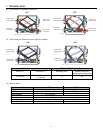
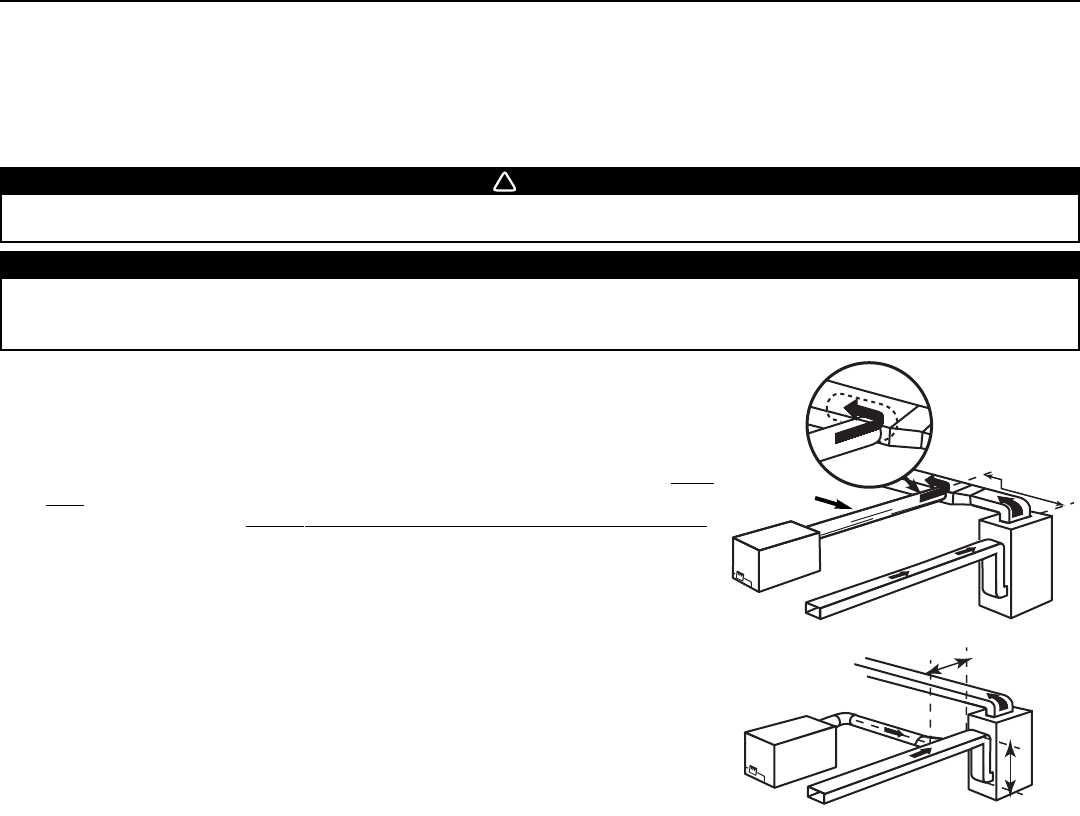
There are 2 methods for connecting the unit to the furnace/air handler:
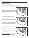
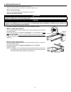
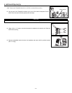
Method 1: Supply side connection
• Cut an opening into the furnace supply duct at least 18 inches (0.5 m) from the
furnace/air handler.
• Connect this opening to the
Fresh air to building
port of the HRV/ERV (use steel
duct, see figure beside).
• Make sure the HRV/ERV duct form an elbow inside the furnace/air handler ductwork.
• If desired, interlock (synchronize) the furnace/air handler blower operation (see
Section 5).
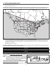
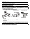
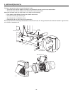
Method 2: Return side connection
• Cut an opening into the furnace return duct not less than 10 feet (3.1 m) from the
furnace/air handler (A+B).
• Connect this opening to the
Fresh air to building
port of the HRV/ERV
(see figure beside).
NOTE: For Method 2, it is not essential that the furnace/air handler runs when the
unit is operation, but we recommend it. If desired, interlock (synchronize) the
furnace/air handler blower operation (see Section 5).
WARNING
When performing duct connections, always use approved tools and materials. Respect all corresponding laws and safety
regulations. Please refer to your local building code.
CAUTION
When performing duct connections to the furnace supply duct, this duct must be sized to support the additional airflow
produced by the HRV/ERV. Also, use a steel duct. It is recommended that the HRV/ERV is running when the furnace is in
operation to prevent backdrafting inside HRV/ERV.
0
!
VJ0036
B
A
VJ0035
MINIMUM 18”
(0.5 M
)
A+B=
NOT LESS
THAN
10’(3.1 M)
STEEL DUCT
- 11 -