


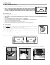
Rigid ducts
Use a small length of flexible duct to connect the rigid duct to the ports in order to avoid vibration transmissions. Use tie-wraps to
perform connections.
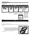
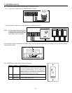
3.7 CONNECTING THE DUCTS TO THE UNIT
Insulated flexible ducts
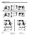
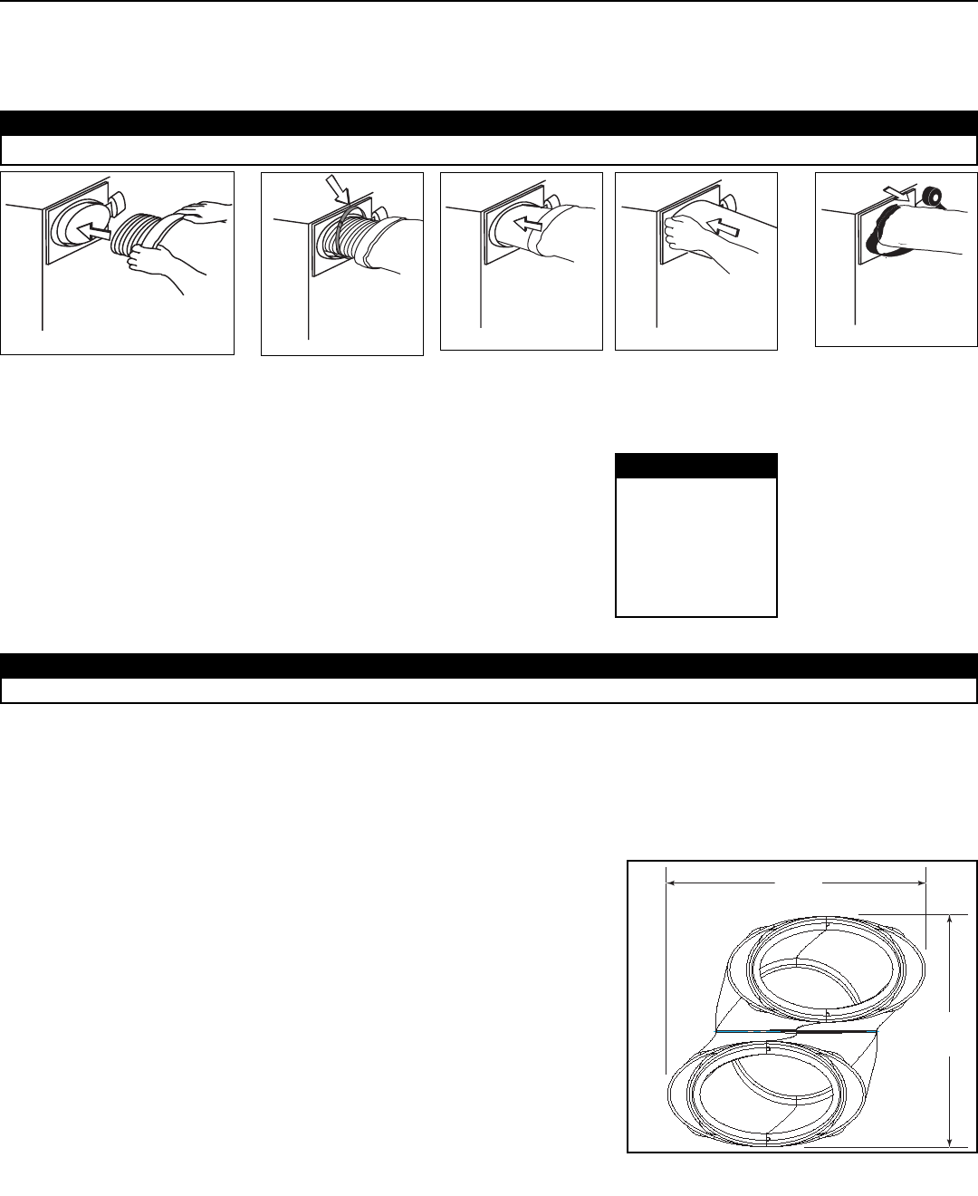
Use the following procedure for connecting the insulated flexible ducts to the port of the unit (
Exhaust air to outside
and
Fresh air from
outside
ports).
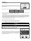
CAUTION
Make sure the vapor
barrier on the
insulated ducts
does not tear during
installation to avoid
condensation within
the ducts.
CAUTION
Do not use screws to connect the rigid ducts to the ports.
CAUTION
Make sure the balancing dampers are set to their appropriate position before connecting the ducts to the ports. See Section 3.3.
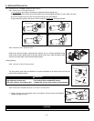
VJ0040
VJ0041
VJ0042
VJ0039
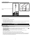
Pull back the insulation to
expose the flexible duct.
Attach the flexible
duct to the port using
tie wrap.
Pull the vapor barrier
over the insulation
and over the outer
ring of the double collar.
Apply duct tape to the
joint making an airtight
seal.Avoid compressing
the insulation when
pulling the tape tightly
around the joint.
Compressed insulation
loses its R value and
causes water dripping
due to condensation
on the exterior surface
of the duct.
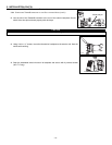
VJ0043
Pull the insulation
over the joint and
tuck in between the
inner and outer rings
of the double collar.
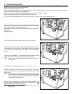
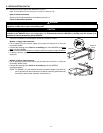
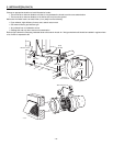
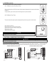
3.8 INSTALLING THE TANDEM® TRANSITION KIT
Use the following procedure for connecting the insulated flexible ducts to the Tandem® transition* (
Exhaust air to outside
and
Fresh air
from outside
).
NOTE: The joist opening needed to install the Tandem® tansition must be
9 3/4” (248 mm) minimum. Also, the maximum height of the Tandem®
transition is 8 3/4” (222 mm). See Tandem® transition end view beside.
If the joist are perpendicular to the ducts, or if the connection to the exterior
hood is in a limited area, your installation will need two exterior hoods
instead of one. In this case, do not use the Tandem® transition kit. See
next Section 3.9 I
NSTALLING 2 EXTERIOR HOODS.
*Patent pending.
VD0118
8 3/4"
222 mm
9 3/4"
248 mm
- 13 -
3. INSTALLATION (CONT’D)